
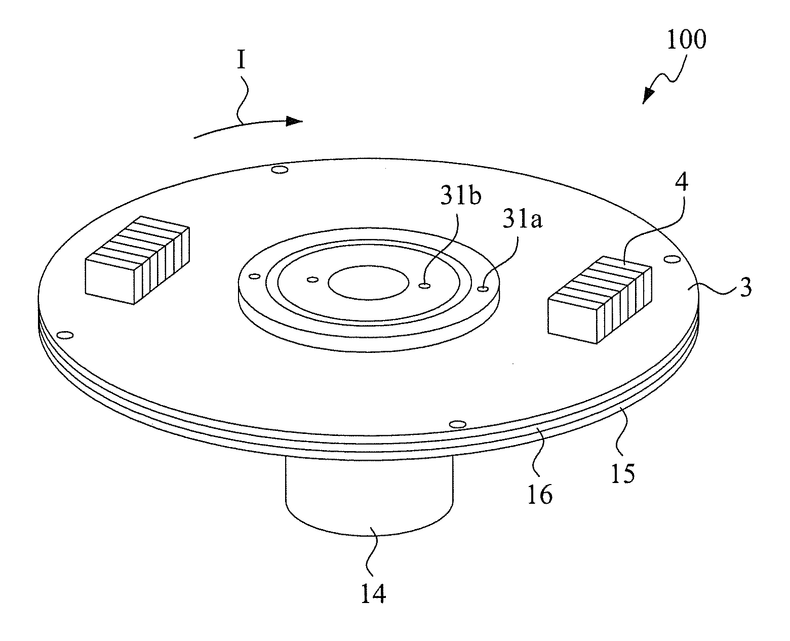
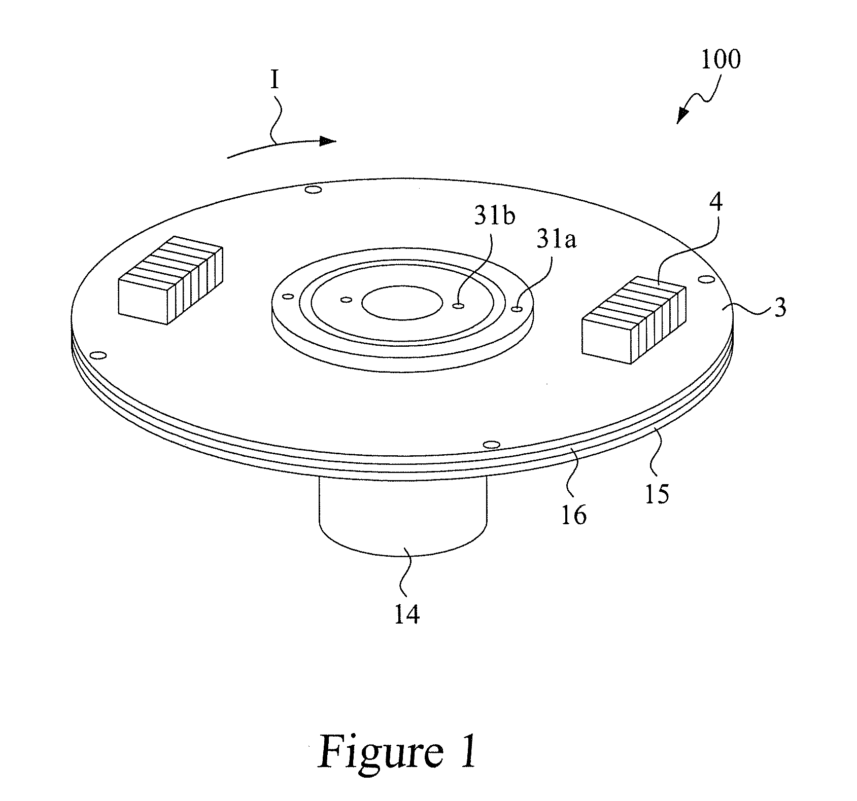
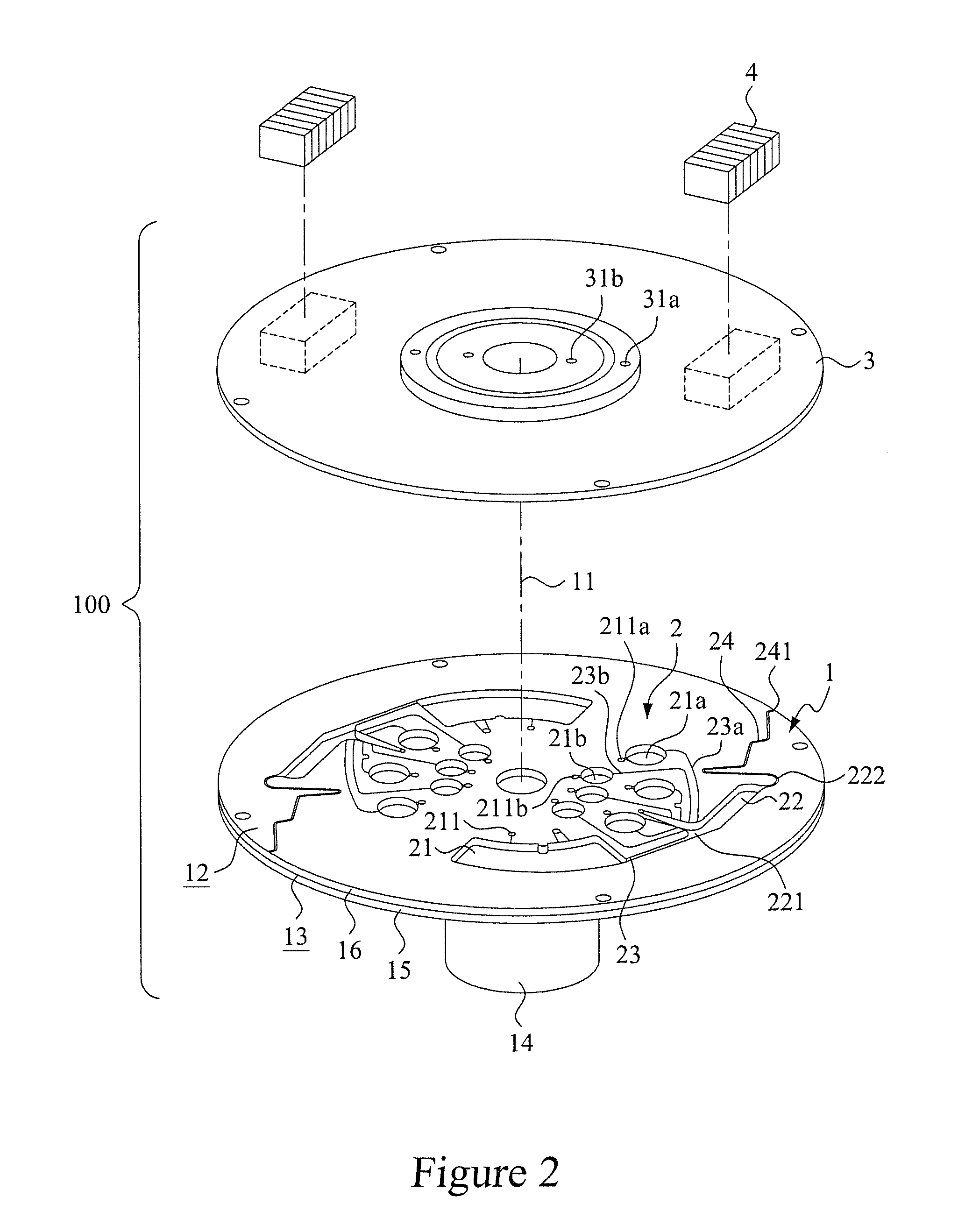
Disk-based fluid sample separation device

a technology of fluid sample and disk, which is applied in the direction of fluid controllers, instruments, laboratory glassware, etc., to achieve the effect of low manufacturing cost and simple process

Inactive Publication Date: 2012-02-02
NAT TAIWAN UNIV
View PDF0 Cites 30 Cited by
  • Summary
  • Abstract
  • Description
  • Claims
  • Application Information

AI Technical Summary

Benefits of technology

The present invention is a device that can capture all magnetically-labeled components in whole blood cells during separation. It is simple to manufacture and can be made using laser machining, CNC machining, micromachining, or injection molding. The material used for manufacturing the device is readily available, leading to low manufacturing costs.

Problems solved by technology

The patent text discusses various techniques for separating fluid samples, such as cells, fetal cells, and rare cells, for various applications like clinical diagnosis and biomedicine research. The main technical problem addressed in the text is the need for efficient and cost-effective methods for separating rare cells from fluid samples, without compromising the quality and quantity of the cells, and without requiring multiple samples or manual transfer operations that may lead to cell loss.

Method used


Image

  • Disk-based fluid sample separation device
  • Disk-based fluid sample separation device
  • Disk-based fluid sample separation device

Examples


third embodiment

[0053]For example, FIG. 18 is a top plan view showing a disk-based fluid sample separation device constructed in accordance with the present invention, and FIG. 19 is a cross-sectional view taken along line 19-19 of FIG. 18. In this embodiment, the disk-based fluid sample separation device, which is designated at 100b, similarly comprises a microfluidic disk 5 that forms a flow channel pattern composed of a plurality of sample storage reservoirs 51 and / or secondary sample storage reservoir(s). A sealing cover 6 is set to cover the microfluidic disk 5. The sealing cover 6 forms air vent channels 61 corresponding to the sample storage reservoirs 51 of the microfluidic disk 5. Each air vent channel 61 has a top end to which an air passage opening / closing control unit 7 (such as a solenoid) is mounted and each air vent channel 61 has a bottom end 61a corresponding to and in fluid communication with the respective sample storage reservoir 51. The top end of each the air vent channel 61 f...

fourth embodiment

[0055]FIG. 22 is a top plan view showing a disk-based fluid sample separation device 100c constructed in accordance with the present invention, and FIG. 23 is a cross-sectional view taken along line 23-23 of FIG. 22. In this embodiment, an arrangement that a single air passage opening / closing control unit 7 is operable for controlling multiple sample storage reservoirs 51 is provided. In other words, the sealing cover 6 has an air vent channel 61 that has a bottom end 61a, which besides being in fluid communication with a sample storage reservoir 51, is in communication with an extended air vent channel 2 for further communicating other sample storage reservoirs 51 through the extended air vent channel 62, whereby when the solenoid 71 of the air passage opening / closing control unit 7 is excited by electrical power applied thereto, the fluid samples contained in the sample storage reservoirs 51 that are in communication with both the air vent channel 61 and the extended air vent chan...


PUM


Abstract

A disk-based fluid sample separation device including at least one air vent forming a part of a flow channel pattern on a microfluidic disk is disclosed. The fluid sample separation device is provided with an air vent sealing cover having at least through hole and is placed on the top surface of the disk. The air vent sealing cover is rotated with respect to the disk either at a first position or a second position. At the first position, the hole of the air vent sealing cover is in correspondence to the air vent of the flow channel pattern to control the sample liquid delivery. At the second position, the air vent of the flow channel pattern is closed. The flow channel pattern includes at least one sample storage reservoir, at least one sample processing reservoir, and at least one communication channel which is in fluid communication between the sample storage reservoir and the sample processing reservoir. In alternative, the status of the hole of the air vent sealing cover is controlled by a control unit.

Description


Claims


Application Information

Patent Timeline
Owner NAT TAIWAN UNIV
Learn More