Dental thermo-forming material

Inactive Publication Date: 2012-02-02
SCHEU DENTAL
View PDF2 Cites 3 Cited by
  • Summary
  • Abstract
  • Description
  • Claims
  • Application Information

AI Technical Summary

Benefits of technology

[0010]This task is solved by the present invention in that the thermo-forming foil or plate is comprised of segments comprised of different materials and lying side by side in the plane of the thermo-forming foil, these materials having different Shore hardness. By way of such a thermo-forming foil or plate comprised of several segments lying side by side and having different Shore hardness, it is possible to produce a splint with differently hard areas in one thermo-forming process only. In this manner, splints individually adapted to the user and to the intended application can be produced, these splints being especially hard or soft in individual areas. The distribution of hard and soft segments in the plane of the foil or plate is freely selectable. In terms of production technique, any arbitrary distributions and hardness differences are feasible.
[0012]One embodiment of the present invention provides for that the thermo-forming foil or plate is comprised of a centrally arranged stripe-shaped reinforcing segment and adjacent symmetrically arranged neutral segments. In this manner, it is feasible to produce splints that are particularly reinforced in the front tooth area. To this effect, the thermo-forming foil is so arranged over the model that the segment having the higher Shore hardness (reinforcing segment) comes to rest over the front teeth, whereas the adjacent neutral segments of the foil having a slightly less Shore hardness rest over the remaining teeth.

Problems solved by technology

However, this always requires an additional process step which entails increased expenditure on time and cost.
A merely local reinforcement of the splint in special dental areas and thus a well-aimed adapted pressure distribution cannot be achieved with these thermo-forming foils.

Method used


Image

  • Dental thermo-forming material
  • Dental thermo-forming material
  • Dental thermo-forming material

Examples


Embodiment Construction

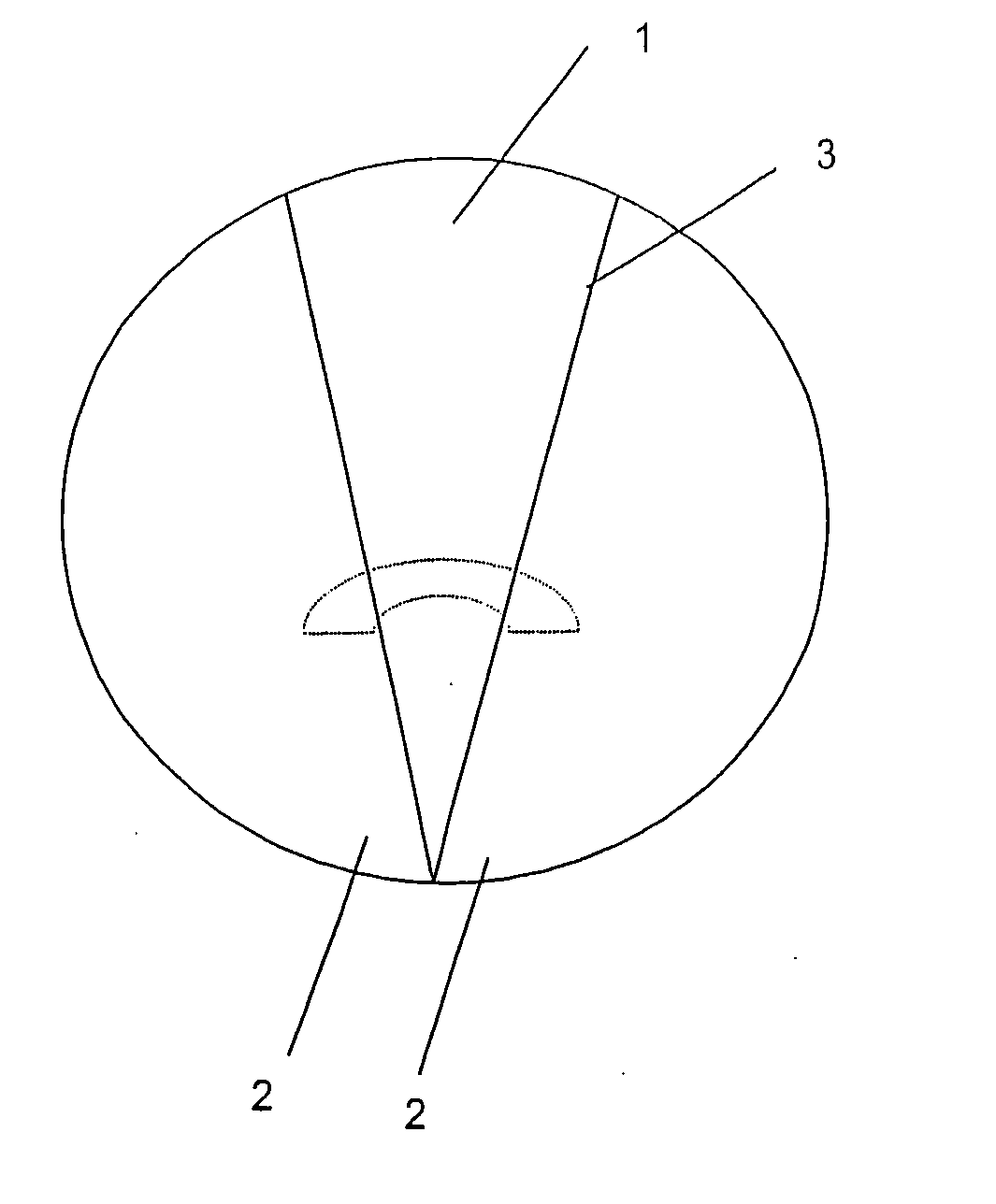
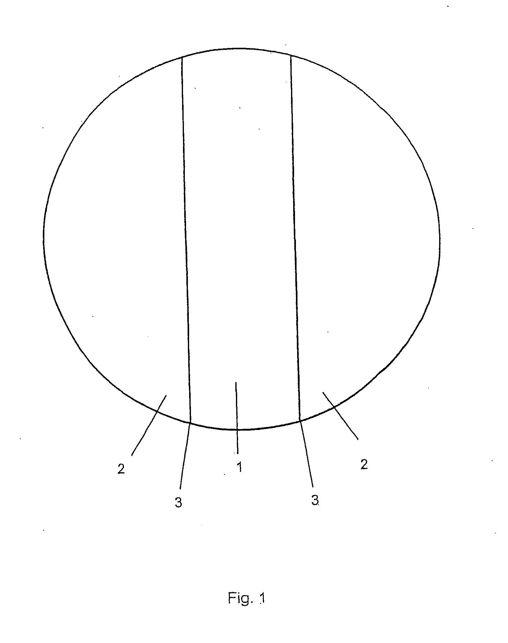
[0025]FIG. 1 illustrates a thermo-forming foil which is comprised of a centrally arranged stripe-shaped reinforcing segment 1 and two adjacent symmetrically arranged neutral segments 2. The reinforcing segment 1 is separated by welding seams 3 from the neutral segments 2.

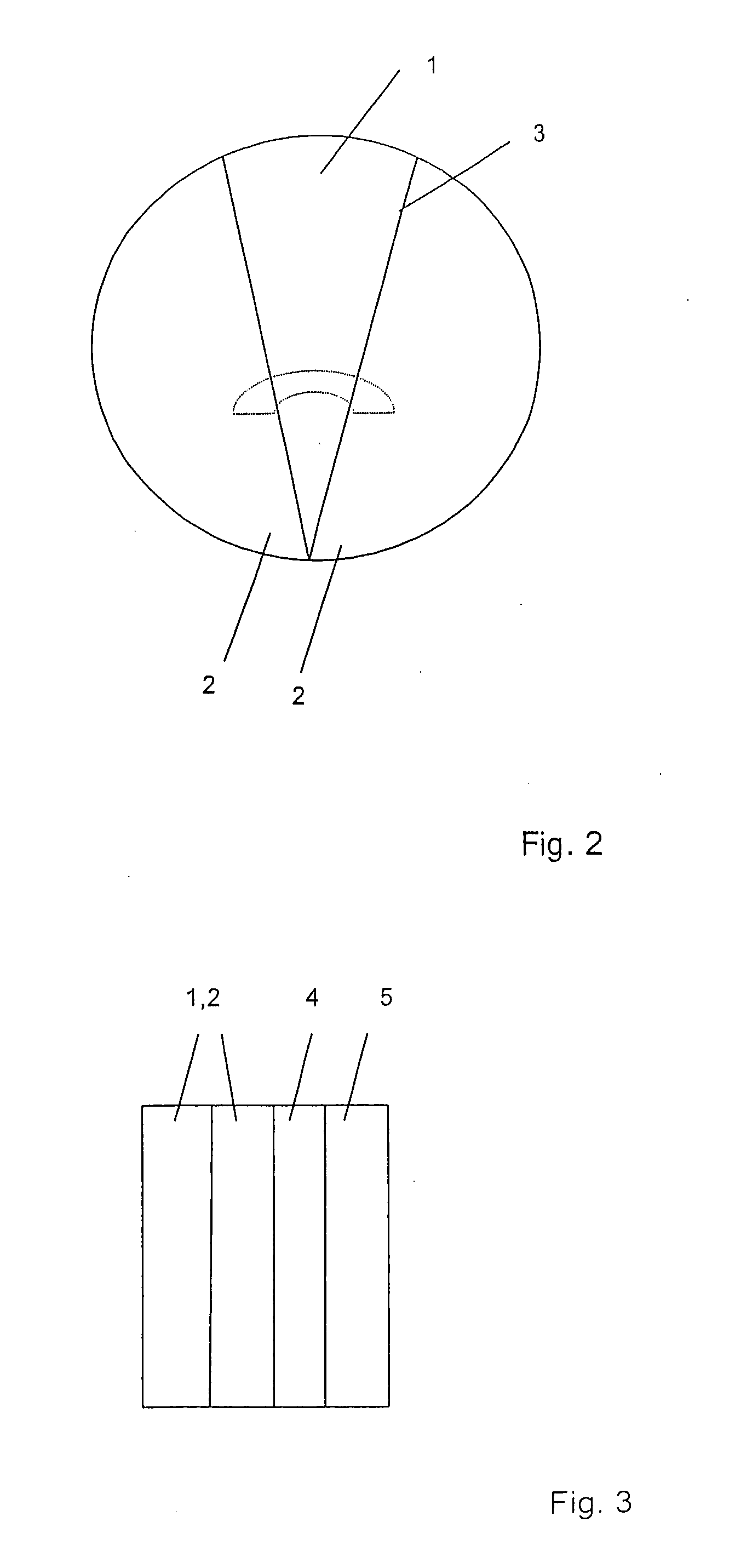
[0026]FIG. 2 shows a thermo-forming foil with a V-shaped reinforcing segment 1 and two adjacent symmetrically arranged neutral segments 2. Arranged under this segment plane is a—not shown—second segment plane which comprises one segment only. This second segment plane is comprised of a material softer than the segments of the first plane.

[0027]The composite according to FIG. 3 in a lateral view shows four planes comprised of thermo-formable material. The outside of the subsequent dental splint is formed by the left side of the foil composite, whereas the inside of the splint is formed by the right side of the foil composite. Viewed from outside to the inside, the thermo-forming foil composite is comprised of the the...


PUM


Abstract

A thermo-forming foil or plate made of a thermoplastic elastomer for the production of dental splints. To integrate reinforcements for various applications into individual areas of the splint, the thermo-forming foil or plate is made of segments comprised of different materials and lying side by side in the plane of the thermo-forming foil or plate, these materials having different Shore hardness.

Description

CROSS REFERENCE TO RELATED APPLICATIONS[0001]Applicant claims priority under 35 U.S.C. 119 of German Application No. 20 2010 010 769.5 filed Jul. 28, 2010.BACKGROUND OF THE INVENTION[0002]The invention relates to a thermo-forming foil or plate made of a thermoplastic elastomer for the production of dental splints.[0003]Thermoplastic plastic foils or plates have been known in thermo-forming technology for a long time.[0004]In thermo-forming technology, a foil or plate which in most applications is comprised of thermoplastic elastomers based on EVA (ethylene vinyl acetate) is softened by heating and drawn over a model to be moulded. After cooling down, the foil or plate thus moulded is removed from the model and subjected to a further precision processing.[0005]Among other applications, special mouthguard splints for use in sports or positioners for correction or stabilization of tooth position can be manufactured in this manner.[0006]For certain applications, more particularly for th...

Claims


Application Information

Patent Timeline
IPC IPC(8): A61C5/14B32B5/00A61C5/90
CPCY10T428/17A61C5/14A61C5/90
Inventor SCHEU, CHRISTIAN
Owner SCHEU DENTAL
Why Eureka
Try Eureka