
Thin film transistor array substrate

Inactive Publication Date: 2012-02-02
CHUNGHWA PICTURE TUBES LTD
View PDF4 Cites 3 Cited by
  • Summary
  • Abstract
  • Description
  • Claims
  • Application Information

AI Technical Summary

Benefits of technology

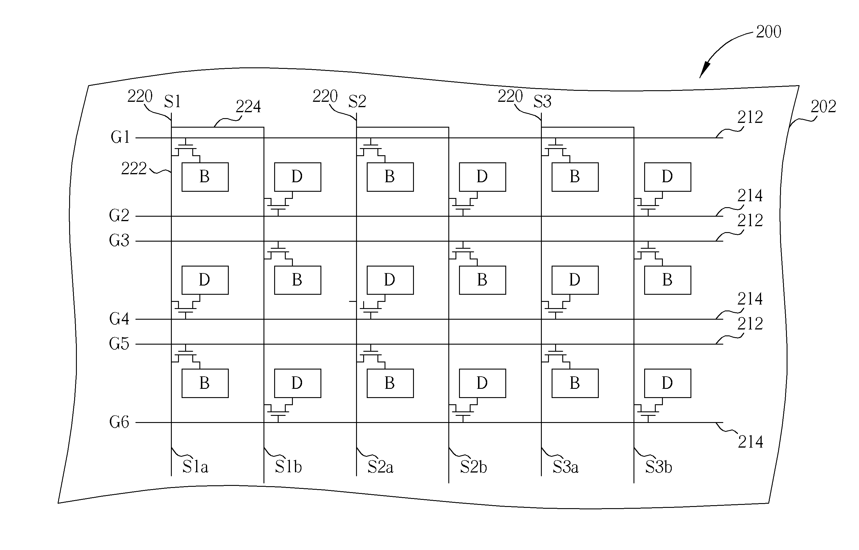
[0011]The present invention provides a TFT array substrate with dual gate design to eliminate bright and dark vertical stripes, and to solve the variation of Cgd of the TFTs due to process misalignment.
[0014]In accordance with the TFT array substrate of the present invention, the source line comprises a main source line and a sub source line connected in parallel. By altering the charge sequence of the TFTs located on the same source line, the arrangement of bright and dark pixel units produced due to the different charge ability of each TFT can be changed. Therefore, the brightness variation can be averaged to avoid the appearance of bright and dark vertical stripes, as a result, the quality of display can be promoted.

Problems solved by technology

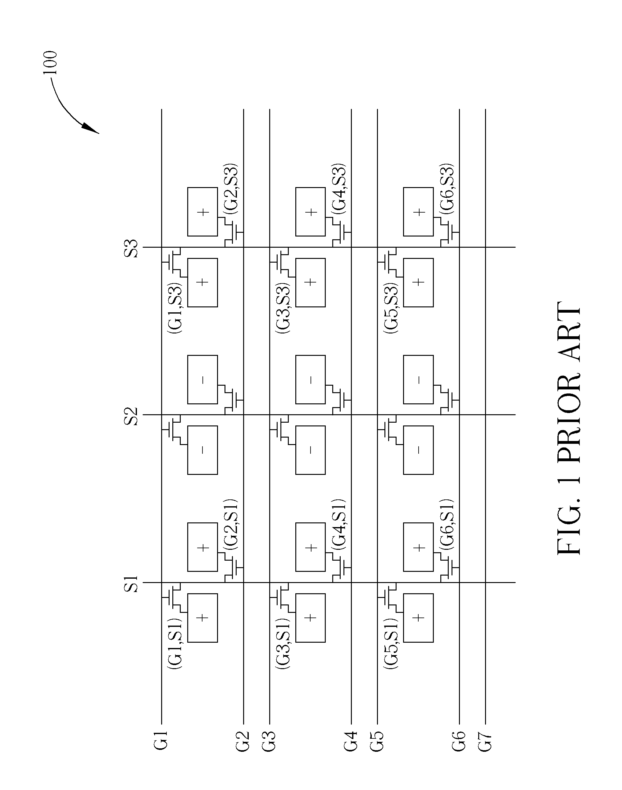
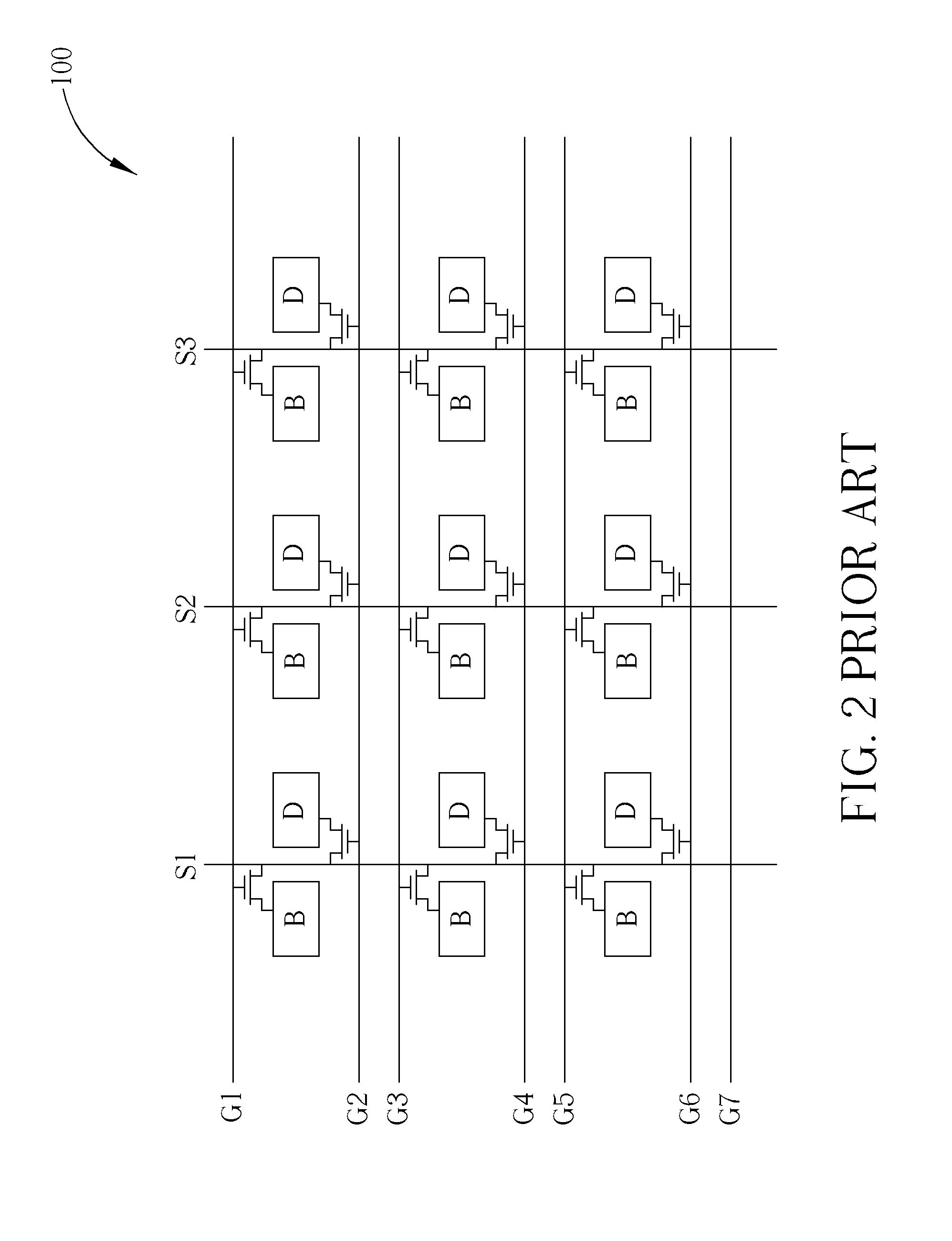
Therefore the charge time of each of the TFTs connected to the gate lines is also reduced by half, and that consequently causes the inconsistence of the charge ability of the adjacent pixels with the same polarity.
. . Sn, which are charged earlier, are incapable of obtaining sufficient charge time to rotate the liquid crystal molecules toward the required direction, thereby causing the leakage of light.
However, when misalignment of respective layers occurs in processing as shown in FIG. 4B, that probably causes the inconsistence of the overlap areas between the gate electrode 122 and the drain electrode 124 of the TFTs 120 separately located on the opposite sides of the same source lines, and further causes the variation of the Cgd and the feedback voltage, as well as the appearance of flicker phenomenon.
Although the conventional technique utilizes the capacitance compensation design to avoid the variation of Cgd of the TFTs separately located on the opposite sides of one of the source line of the dual-gate type display panel, this method is criticized for the higher cost due to its complicated processing.

Method used


Image

  • Thin film transistor array substrate
  • Thin film transistor array substrate
  • Thin film transistor array substrate

Examples


Embodiment Construction

[0021]Certain terms are used throughout the description and following claims to refer to particular components. As one skilled in the art will appreciate, manufacturers may refer to a component by different names. This document does not intend to distinguish between components that differ in name but in function. In the following discussion and in the claims, the terms “include”, “including”, “comprise”, and “comprising” are used in an open-ended fashion, and thus should be interpreted to mean “including, but not limited to . . . ” The terms “electrically connect” and “electrically connected” are intended to mean either an indirect or a direct electrical connection. Thus, if a first device electrically connects a second device, that connection may be through a direct electrical connection, or through an indirect electrical connection via other panels and connections.

[0022]Please refer to FIG. 5 and FIG. 6. FIG. 5 and FIG. 6 are diagrams illustrating a TFT array substrate with dual g...


PUM


Abstract

A thin film transistor array substrate includes a substrate having a plurality of pixel units arranged in a matrix, a plurality of first gate lines and second gate lines alternately arranged on the substrate, a plurality of source lines perpendicular to the first gate lines and the second gate lines formed on the substrate, and a plurality of thin film transistors respectively positioned in the pixel units. Each of the source lines further includes a main source line and a sub source line electrically connected to each other in parallel connection.

Description

BACKGROUND OF THE INVENTION[0001]1. Field of the Invention[0002]The present invention is related to a thin film transistor (TFT) array substrate, and more particularly, to a TFT array substrate with dual gate design.[0003]2. Description of the Prior Art[0004]A conventional liquid crystal display (LCD) panel comprises a TFT array substrate and a color filter array substrate opposite to each other, and a liquid crystal layer positioned between the TFT array substrate and the color filter array substrate. Moreover, the TFT array substrate comprises a plurality of TFTs arranged in a matrix, as well as a plurality of gate lines and a plurality of source lines electrically connected to the TFTs. Furthermore, the color filter array substrate at least comprises a plurality of color filters for displaying colorful images, and a black matrix for preventing the leakage of light.[0005]Based on different driving modes, the LCD panels can be classified as: single-gate type display panels and dual...

Claims


Application Information

Patent Timeline
IPC IPC(8): H01L27/15
CPCH01L29/41733H01L27/124
Inventor HO, SHIUAN-YI
Owner CHUNGHWA PICTURE TUBES LTD
Learn More