Motor with speed reduction mechanism

a technology of speed reduction mechanism and motor, which is applied in the direction of mechanical energy handling, wing accessories, coupling device connections, etc., can solve the problems of downsizing the motor with speed reduction mechanism, reduce the size of the connector junction in the lateral direction, and reduce the size of the connector junction

Inactive Publication Date: 2012-02-02
MITSUBA CORP
View PDF4 Cites 13 Cited by
  • Summary
  • Abstract
  • Description
  • Claims
  • Application Information

AI Technical Summary

Benefits of technology

[0005]However, according to the motor with speed reduction mechanism disclosed in Japanese Patent Application Laid-Open Publication No. 2008-141912, the power supply terminal and the ground terminal are situated close to each other in the connector opening portion and arranged side by side in its lateral direction, so it is necessary to size up the connector opening portion to some extent in its lateral direction. That is, a sufficient air gap is secured (insulation property is secured) between the power supply terminal and the ground terminal by sizing up the connector opening portion to some extent in its lateral direction, so it is possible to guarantee the stable operation of the motor with speed reduction mechanism for a long period of time. Therefore, in the motor with speed reduction mechanism disclosed in Japanese Patent Application Laid-Open Publication No. 2008-141912, the size of the connector opening portion may cause a problem in downsizing of the motor with speed reduction mechanism.
[0006]An object of the invention is to provide a motor with speed reduction mechanism improved so as to downsize a connector junction while securing a sufficient air gap between a power supply terminal and a ground terminal.
[0011]According to the present invention, since two of the power supply conductive members are respectively used as power supply conductive members, the other six power supply conductive members are respectively used as control conductive members, one end portions of the power supply conductive members are respectively disposed on both sides of the connector junction in longitudinal direction, and one end portions of the control conductive members are disposed between the power supply conductive members, arranged in two rows in longitudinal direction, and arranged in three rows in lateral direction, it is possible to separate one end portions of the power supply conductive members from each other. Therefore, it is possible to reduce the connector junction in size while securing a sufficient air gap between one end portions of the power supply conductive members. Further, it is possible to reduce the motor with speed reduction mechanism in size.
[0012]According to the present invention, since each of the power supply conductive members is formed into a flat plate, each of the control conductive members is formed into a needle shape, and one end portions of the power supply conductive members are disposed in the connector junction so that the longitudinal direction of the power supply conductive members becomes parallel with the longitudinal direction of the connector junction, it is possible to reduce the connector junction in size in lateral direction.
[0013]According to the present invention, since the motor with speed reduction mechanism is a power window motor mounted on an automobile, one end portions of the power supply conductive members are respectively used as a power supply terminal and a ground terminal, and one end portions of the control conductive members are respectively used as a window automatic opening / closing terminal, a window lifting terminal, a window lowering terminal, an ignition detecting terminal, a serial communication terminal, and a spare terminal, it is possible to reduce the power window device in size, while securing functions necessary as the power window device.

Problems solved by technology

Therefore, in the motor with speed reduction mechanism disclosed in Japanese Patent Application Laid-Open Publication No. 2008-141912, the size of the connector opening portion may cause a problem in downsizing of the motor with speed reduction mechanism.

Method used


Image

  • Motor with speed reduction mechanism
  • Motor with speed reduction mechanism
  • Motor with speed reduction mechanism

Examples


first embodiment

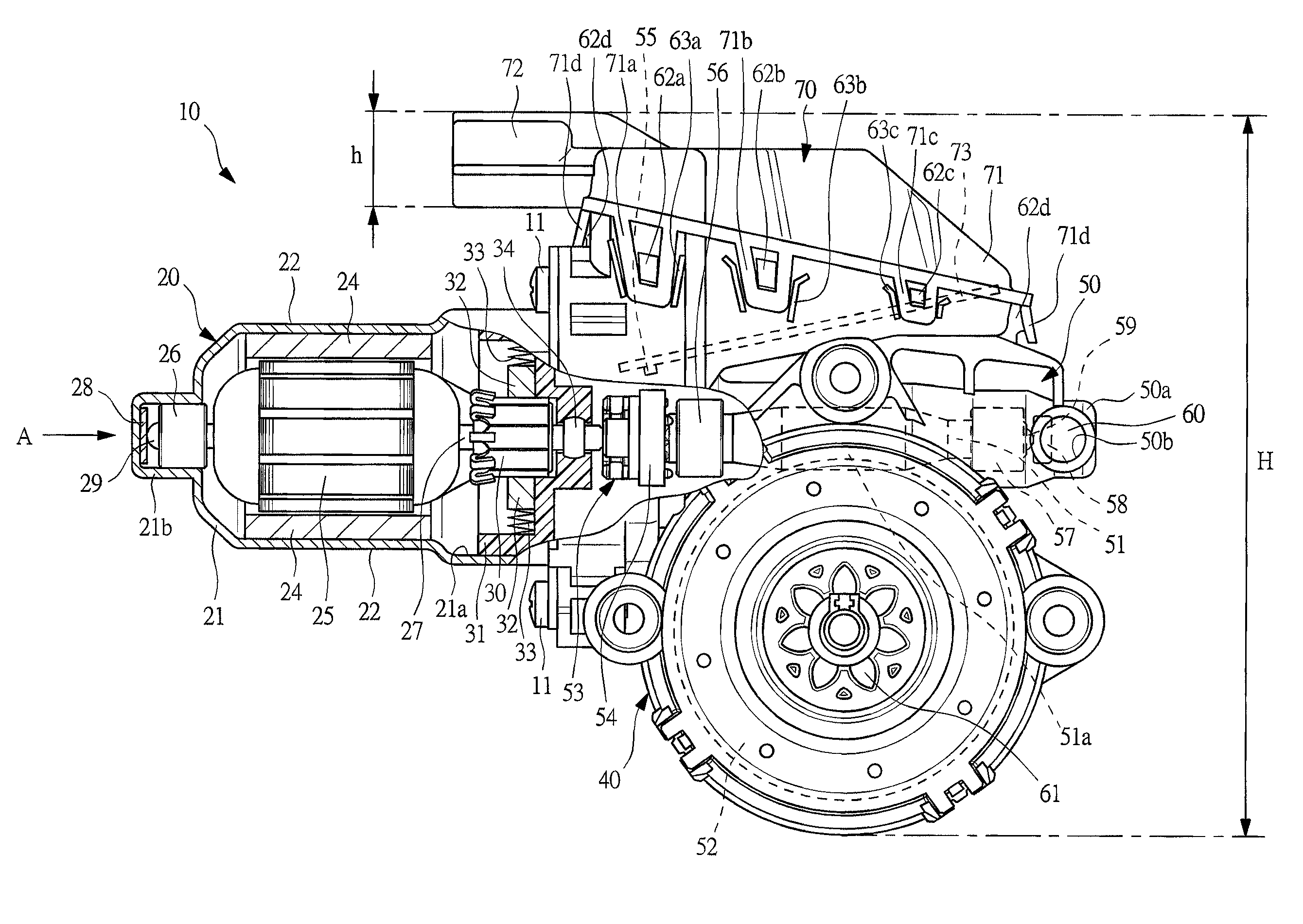
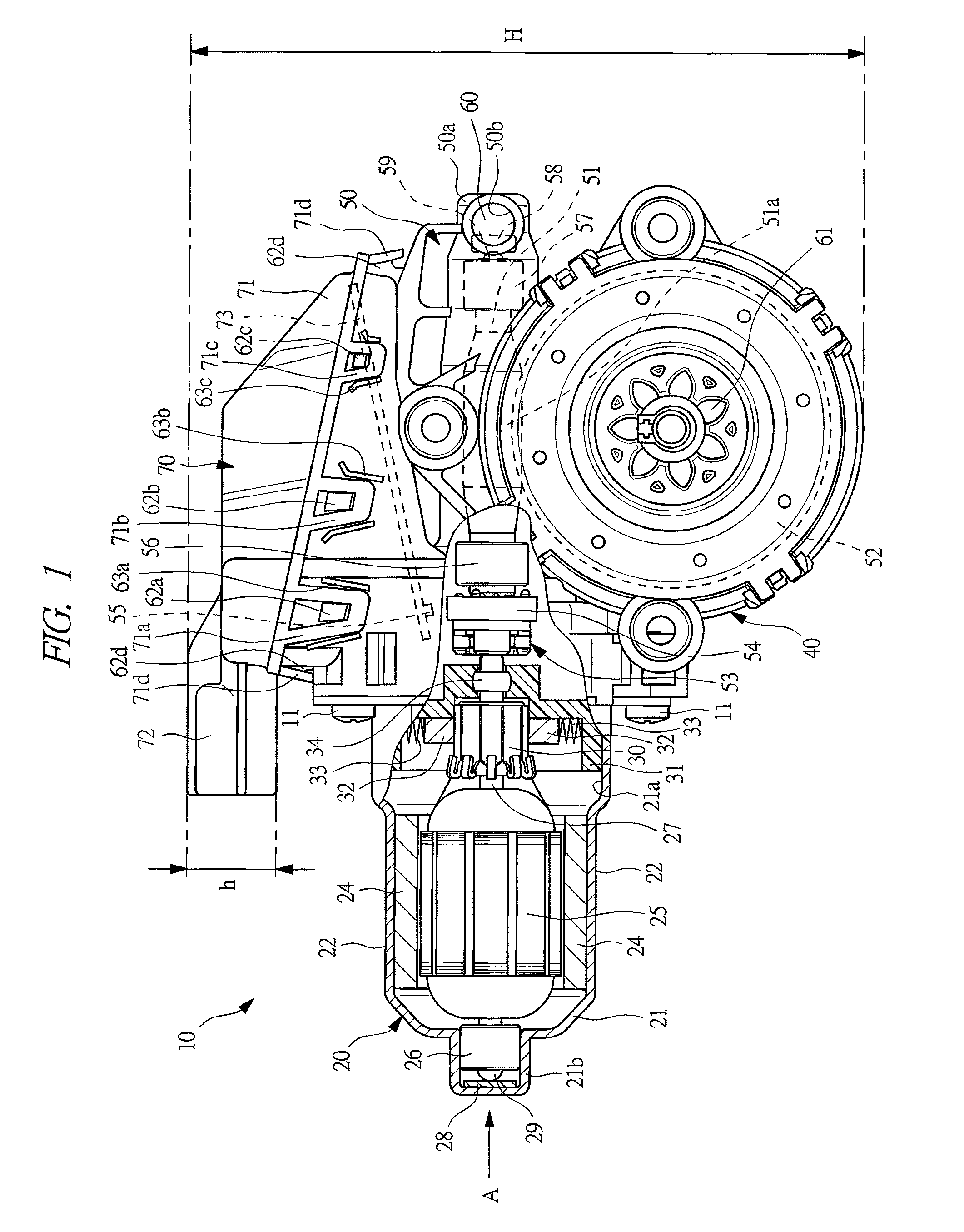
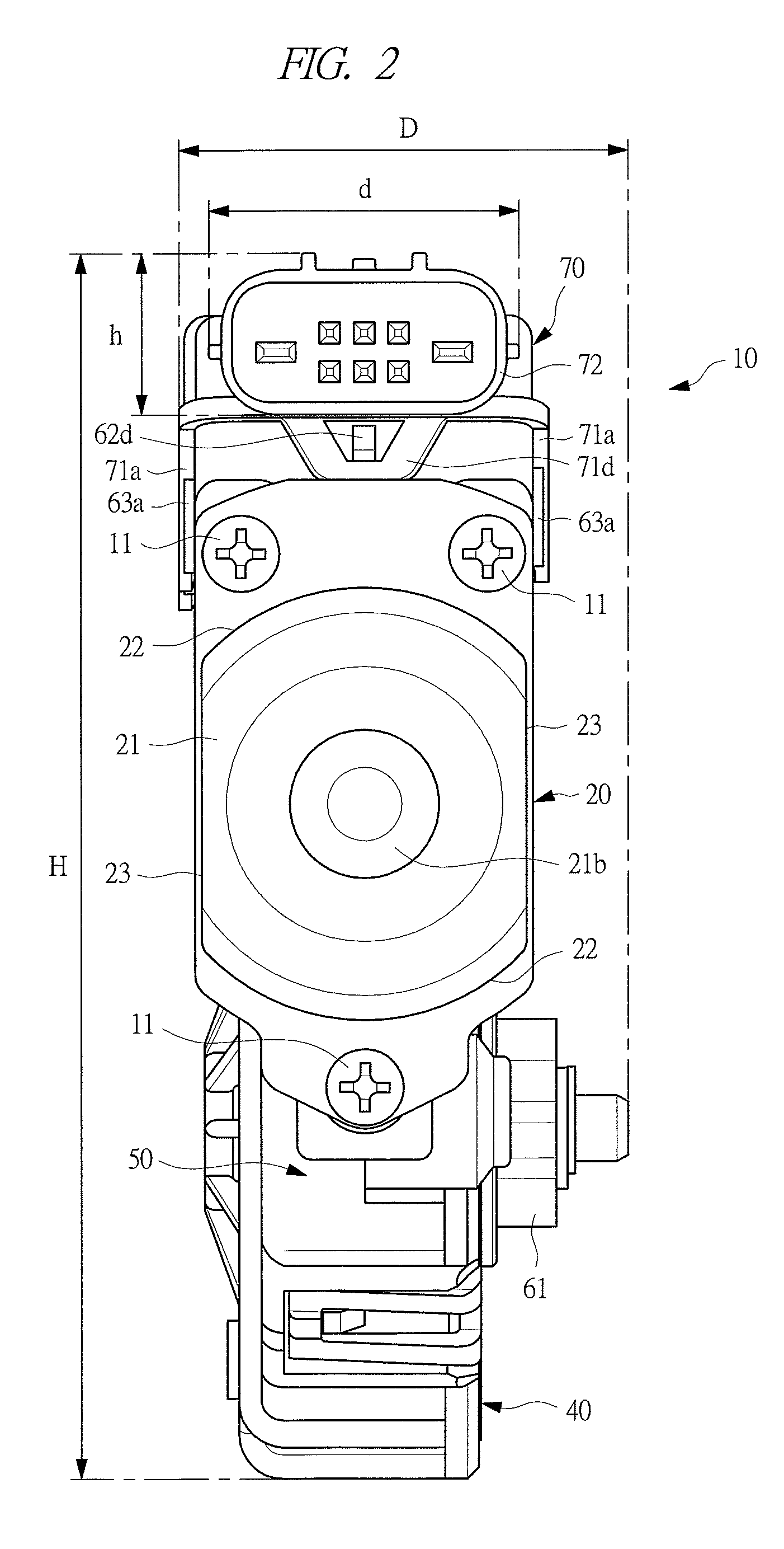
[0022]FIG. 1 is a partial cross-sectional view showing a power window motor according to the FIG. 2 is a view of the power window motor shown in FIG. 1 seen from the direction of an arrow “A”. FIG. 3 is a perspective view showing the inside of a connector member. FIG. 4 is an enlarged view of a portion “B” circled by a dashed line in FIG. 3. FIG. 5 is a view of the connector member shown in FIG. 3 seen from the direction of an arrow “C”. FIG. 6 is a view for explaining a procedure of assembling the power window motor.

[0023]As shown in FIGS. 1 and 2, a power window motor 10 as a motor with speed reduction mechanism is used as a drive source of a power window device (not shown) mounted on a vehicle such as an automobile and the like. The power window motor 10 is adapted to drive a window regulator (not shown) to lift up and down a window glass (not shown) provided to a door and the like of a vehicle. Since the power window motor 10 is installed in a narrow space (not shown) formed in...

second embodiment

[0058]FIG. 7 is a partial cross-sectional view showing a power window motor according to the present invention.

[0059]As shown in FIG. 7, a power window motor 80 according to the second embodiment is different, as compared with the power window motor 10 of the first embodiment described above, in that a single rotating shaft 81 is provided by integrating the armature shaft 27 with the worm shaft 51 and a connector junction 86 opens toward the side opposite to the side where the pinion 61 is disposed (refer to FIG. 1).

[0060]The rotating shaft 81 passes through and fixed to the center of rotation of the armature 25. One end (right side in the drawing) of the rotating shaft 81 is disposed inside a yoke 21 and rotatably supported by a bottomed cylinder portion 21b of the yoke 21 via a first radial bearing 26, a first thrust bearing 28, and a first steel ball 29. The other end portion (left side in the drawing) of the rotating shaft 81 is provided in a gear case 50 and rotatably supported...


PUM


Abstract

A power supply terminal 76a and a ground terminal 76b are respectively disposed on both sides of a connector junction 72 in longitudinal direction, and the control terminals 77a to 77f are disposed between the power supply terminal 76a and the ground terminal 76b, arranged in two rows in longitudinal direction of the connector junction 72, and arranged in three rows in lateral direction of the connector junction 72. Therefore, it is possible to separate the power supply terminal 76a from the ground terminal 76b. And it is possible to reduce the connector junction 72 in size while securing a sufficient air gap (distance L) between the power supply terminal 76a and the ground terminal 76b. Further, it is possible to reduce the power window motor in size.

Description

CROSS REFERENCE TO RELATED APPLICATIONS[0001]This application is entitled to the benefit of and incorporates by reference essential subject matter disclosed in International Patent Application No. PCT / JP2010 / 054352 filed on Mar. 15, 2010 and Japanese Patent Application No. 2009-073529 filed Mar. 25, 2009.TECHNICAL FIELD[0002]The present invention relates to a motor with speed reduction mechanism having a speed reduction mechanism for reducing the speed of rotation of a rotating shaft and outputting the speed-reduced rotation and a controller for controlling the rotation of the rotating shaft.BACKGROUND ART[0003]Conventionally, a motor with speed reduction mechanism capable of obtaining a large output in spite of its small size is used as a drive source of a power window device to be mounted on a vehicle such as an automobile and the like. When an operator operates an operation switch provided in a passenger compartment and the like, the motor with speed reduction mechanism is driven...

Claims


Application Information

Patent Timeline
Patent Type & Authority Applications(United States)
IPC IPC(8): H02K11/00
CPCH01R13/6271H02K5/225E05F15/697H02K11/0084E05Y2900/55H02K7/1166H02K11/38
Inventor SHIBUSAWA, HIROYUKIMITA, MASAKI
Owner MITSUBA CORP
Why Eureka
Try Eureka