Rotor of a permanent magnet synchronous machine

a synchronous machine and permanent magnet technology, applied in the direction of dynamo-electric machines, magnetic circuit rotating parts, magnetic circuit shapes/forms/construction, etc., can solve the problems of undesirably high degrees of heating in the laminate stack of stator and rotor, undesirably high degrees of heating in the stator and rotor, and the harmonics of the magnetic air gap field, and the effect of reducing the harmonics of the magnetic air gap

Inactive Publication Date: 2012-02-02
SIEMENS AG
View PDF14 Cites 27 Cited by
  • Summary
  • Abstract
  • Description
  • Claims
  • Application Information

AI Technical Summary

Benefits of technology

[0008]Enlarging the magnetic air gap at the pole edges results in a reduction in the harmonics of the magnetic air-gap field of the permanent magnet synchronous machine. Thus, eddy current losses and hysteresis losses in the core of the stator and the rotor are reduced. By virtue of splitting a magnetic pole advantageously into a plurality of isolated individual magnets, eddy current losses in the electrically conductive permanent magnets are additionally reduced. This results in dynamoelectric machines with a comparatively high power.
[0010]In order that the torque ripple is thus virtually uniform, further-reaching, known measures, such as skewing of the magnetic pole, for example, can be dispensed with, which simplifies the manufacture of the rotor and therefore reduces costs.
[0011]By virtue of the filling elements and the banding, a virtually cylindrical circumferential surface of the rotor is now provided. Owing to this now cylindrical circumferential surface of the rotor, air friction losses, in particular at high rotation speeds, in the air gap of the permanent magnet synchronous machine are kept comparatively low during operation of said machine.

Problems solved by technology

Dynamoelectric permanent magnet synchronous machines for high circumferential speeds usually have high core losses and eddy current losses.
This results in undesirably high degrees of heating in the laminate stack of the stator and rotor and on the permanent magnets of the rotor.

Method used


Image

  • Rotor of a permanent magnet synchronous machine
  • Rotor of a permanent magnet synchronous machine
  • Rotor of a permanent magnet synchronous machine

Examples


Embodiment Construction

[0018]Throughout all the figures, same or corresponding elements may generally be indicated by same reference numerals. These depicted embodiments are to be understood as illustrative of the invention and not as limiting in any way. It should also be understood that the figures are not necessarily to scale and that the embodiments are sometimes illustrated by graphic symbols, phantom lines, diagrammatic representations and fragmentary views. In certain instances, details which are not necessary for an understanding of the present invention or which render other details difficult to perceive may have been omitted.

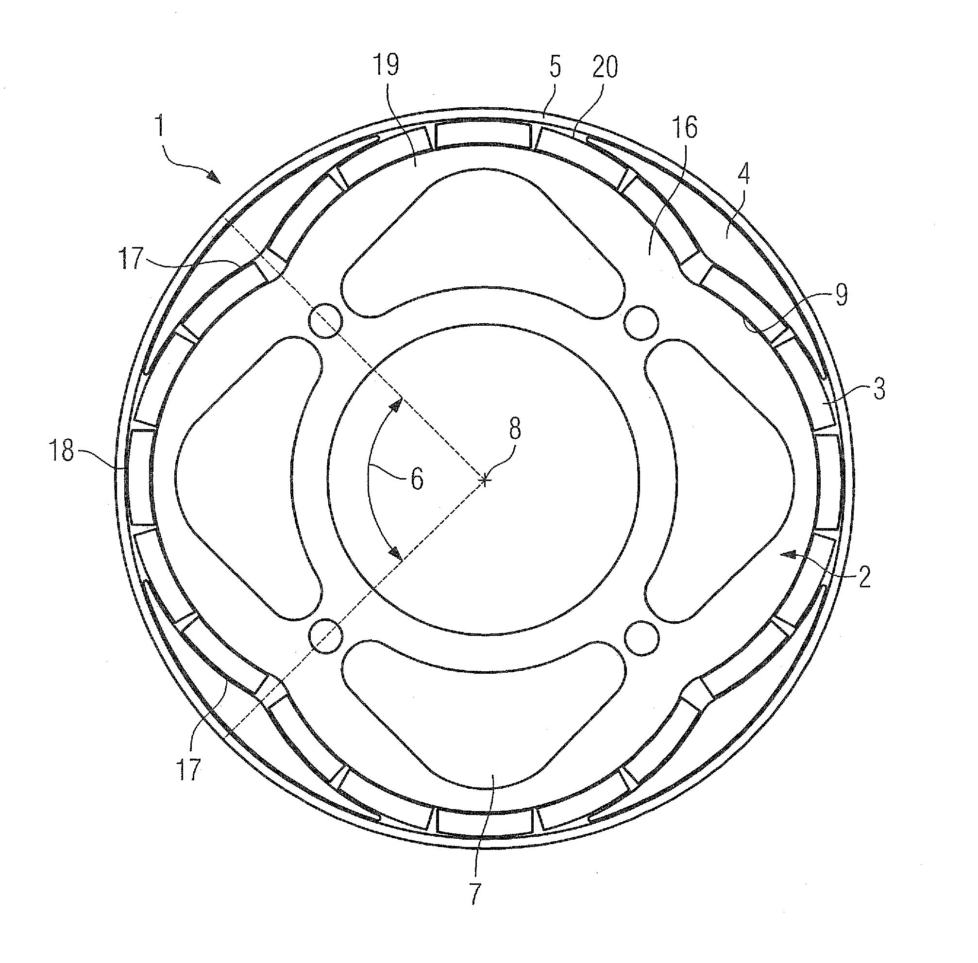
[0019]Turning now to the drawing, and in particular to FIG. 1, there is shown a cross sectional view of one embodiment of a rotor according to the present invention, generally designated by reference numeral 1. The rotor 1 has a basic body 16 made of layered laminates 2 and having cutouts 7 for cooling on one hand, and providing reduced inertia of the rotor 1 on the other ha...


PUM


Abstract

A rotor for a permanent magnet synchronous machine includes a basic body defining a center. Permanent magnets are arranged on a circumferential surface of the basic body to thereby form magnetic poles. Each magnetic pole is formed in a circumferential direction by at least two permanent magnets and defined by a pole center and a pole edge, wherein the pole edge is spaced from the center of the basic body at a distance which is smaller than a distance of the pole center to the center of the basic body. Positioned in sections between the pole centers of adjacent pole are filling elements, with a banding securing the filling elements on the permanent magnets in such a way that the rotor has a substantially cylindrical circumferential surface.

Description

CROSS-REFERENCES TO RELATED APPLICATIONS[0001]This application claims the priority of German Patent Application, Serial No. 10 2010 001 481.8, filed Feb. 2, 2010, pursuant to 35 U.S.C. 119(a)-(d), the content of which is incorporated herein by reference in its entirety as if fully set forth herein.BACKGROUND OF THE INVENTION[0002]The present invention relates to a rotor of a permanent magnet synchronous machine, and more particularly for a rotor of a permanent magnet synchronous machine operating at high rotation speeds.[0003]The following discussion of related art is provided to assist the reader in understanding the advantages of the invention, and is not to be construed as an admission that this related art is prior art to this invention.[0004]Dynamoelectric permanent magnet synchronous machines for high circumferential speeds usually have high core losses and eddy current losses. This results in undesirably high degrees of heating in the laminate stack of the stator and rotor an...

Claims


Application Information

Patent Timeline
Patent Type & Authority Applications(United States)
IPC IPC(8): H02K1/28
CPCH02K1/278H02K1/2781
Inventor BACH, DOMINIKMADER, DANIELVOLLMER, ROLF
Owner SIEMENS AG
Why Eureka
Try Eureka