
Display device having repair and detect structure

a technology of detecting structure and display device, which is applied in the direction of static indicating device, instruments, optics, etc., can solve the problems of increasing process difficulty, narrow line width, and difficulty in reducing the resistance of conducting lines, so as to reduce the number of conducting lines and maximize the utilization of substrate area.

Inactive Publication Date: 2012-02-02
CHUNGHWA PICTURE TUBES LTD
View PDF0 Cites 19 Cited by
  • Summary
  • Abstract
  • Description
  • Claims
  • Application Information

AI Technical Summary

Benefits of technology

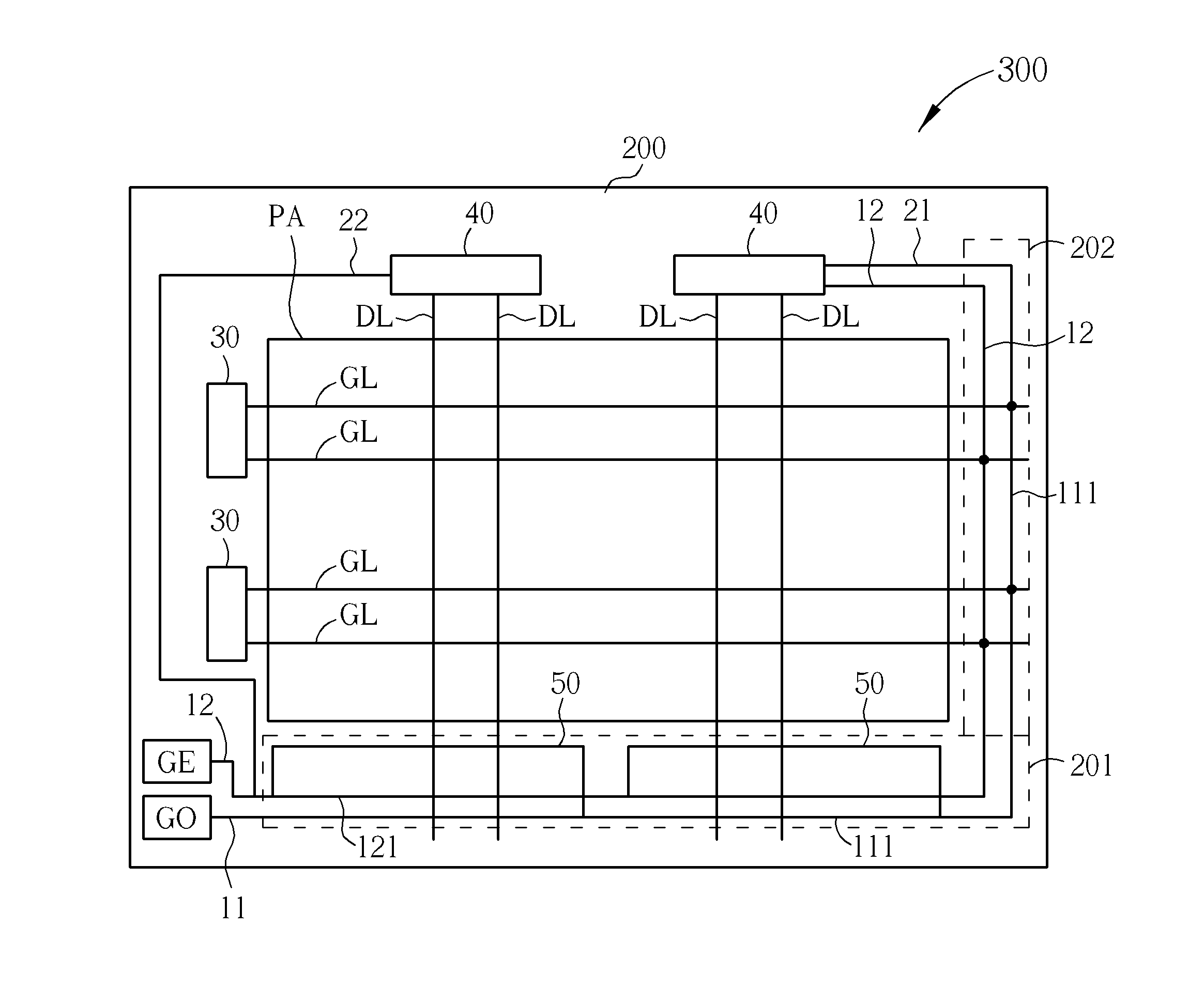
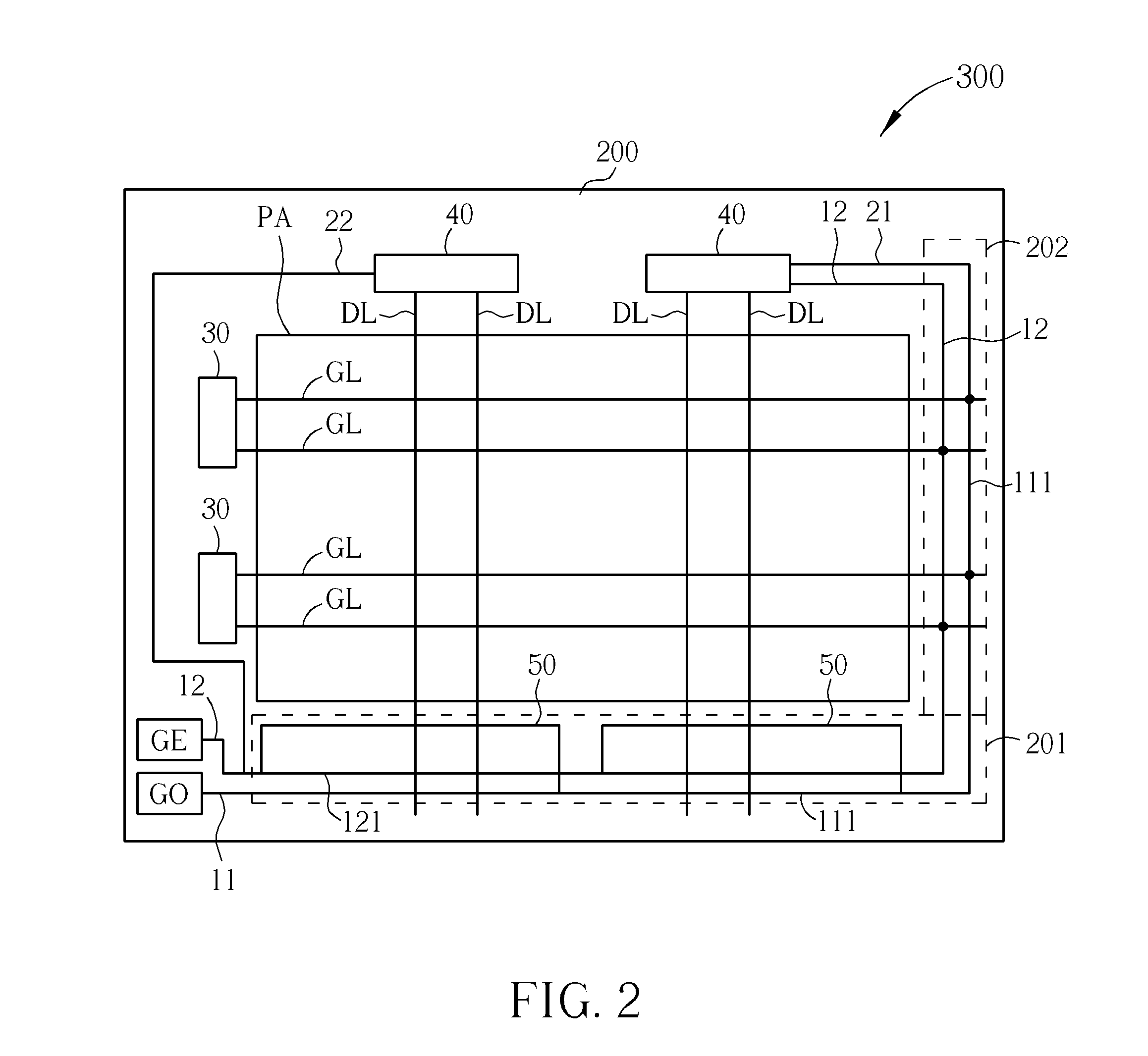
[0010]To decrease the number of conducting lines, the display device having repair and detect structure in the present invention utilizes a first shorting segment electrically connected to the first repair line to combine the first repair line and the first shorting bar. Further, the display device having repair and detect structure in the present invention utilizes the first repair segment of the first repair line overlapping with the first shorting segment of the first shorting bar. Consequently, the first repair segment shares the same region of the substrate with the first shorting segment, and the area of the substrate is utilized more effectively.

Problems solved by technology

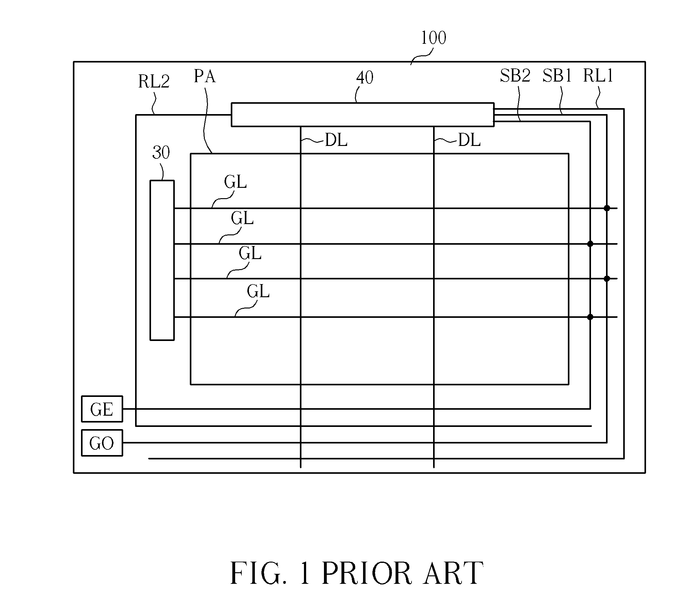
In addition, when the display area of display device is enlarged and when the resolution is elevated, more data lines are required and the width of line gets narrower, which increases process difficulty.
In the circumstance of limited space of the peripheral region, the number of repair lines disposed and the line width is restricted, which makes it difficult to reduce the resistances of the conducting lines, and unfavorable to the progress of repairing and detecting.
Accordingly, the conventional device suffers the problems of insufficient space for repair lines and the higher resistance.

Method used


Image

  • Display device having repair and detect structure
  • Display device having repair and detect structure
  • Display device having repair and detect structure

Examples


Embodiment Construction

[0018]Certain terms are used throughout the following descriptions and claims to refer to particular components. As one skilled in the art will appreciate, manufacturers may refer to a component by different names. This document does not intend to distinguish between components that differ in name but in function. In the following discussion and in the claims, the terms “include” and “comprise” are used in an open-ended fashion, and thus should be interpreted to mean “including, but not limited to . . . ”. In addition, the term “electrically connected” includes any directly or indirectly electrical connection methods. Therefore, if the description in the following paragraphs is that a first device is electrically connected to a second device, the aforementioned words stand for that the first device can be electrically connected to the second device directly or be electrically connected to the second device indirectly by means of other devices or electrical connection methods. Furthe...


PUM


Abstract

A display device having repair and detect structure includes a substrate, a pixel array, a first shorting bar and a first repair line. The pixel array disposed on the substrate includes a plurality of data lines and a plurality of gate lines. The first shorting bar disposed on the substrate is connected to the gate lines for testing the gate lines, and the first shorting bar includes a first shorting segment. The first repair line is disposed on the substrate for repairing at least one of the data lines. The first shorting segment of the first shorting bar is electrically connected to the first repair line. Furthermore, another repair and detect structure of a display device is disclosed, wherein the first shorting bar includes a first shorting segment, the first repair line includes a first repair segment, and the first shorting segment overlaps with the first repair segment.

Description

BACKGROUND OF THE INVENTION[0001]1. Field of the Invention[0002]The present invention is related to a display device having repair and detect structure, and more particularly, to a display device having repair and detect structure in which a first shorting segment of the first shorting bar is electrically connected to a first repair line, furthermore, or a first repair segment of the first repair line overlaps with a first shorting segment of a first shorting bar.[0003]2. Description of the Prior Art[0004]Please refer to FIG. 1. FIG. 1 illustrates a schematic diagram of a conventional display device having repair and detect structure. As shown in FIG. 1, the display device having repair and detect structure comprises a substrate 100, a pixel array PA, a first shorting bar SB1, a second shorting bar SB2, a first repair line RL1, a second repair line RL2, a gate driver chip 30 and a source driver chip 40. The pixel array PA comprises a plurality of data lines DL and a plurality of gat...

Claims


Application Information

Patent Timeline
Patent Type & Authority Applications(United States)
IPC IPC(8): G01R31/02
CPCG09G3/006H01L27/1244G09G2330/08G09G2300/0426G02F1/136259G02F1/136263
Inventor CHANG, KAI-TINGHSU, HAN-TUNGZEN, TSU-TE
Owner CHUNGHWA PICTURE TUBES LTD
Learn More