Electronic plunger switch

a technology of electronic components and plunger switches, applied in the direction of electric switches, basic electric elements, electric apparatus, etc., can solve the problems of reducing the service life of plunger switches, affecting the service life of electronic components with lubricants, and unable to ensure, so as to increase the number of cycles

Active Publication Date: 2012-02-02
KISSLING ELEKTROTECHNIK GMBH & CO KG
View PDF2 Cites 0 Cited by
  • Summary
  • Abstract
  • Description
  • Claims
  • Application Information

AI Technical Summary

Benefits of technology

[0011]By contrast with this prior art, the object of the present invention is to create, using the simplest technical means and in the most uncomplicated, inexpensive way, a plunger switch of the type described at the beginning, which is equipped with an electronic sensor unit and despite the use of moving mechanical parts, makes it possible to significantly increase the number of cycles to a figure greater than 4 million actuations over the service life of the plunger switch.

Problems solved by technology

However, this is only possible through the cooperation according to the invention with the means for protecting the electronic sensor unit from the penetration of lubricating fluid because otherwise, the service life of the plunger switch would be drastically reduced again by damage to the sensor unit since even with the selection of a nonaggressive lubricating fluid, it is almost impossible to ensure that continuous contact of the electronic components with the lubricant will not result in damage at some point in time.

Method used


Image

  • Electronic plunger switch
  • Electronic plunger switch
  • Electronic plunger switch

Examples


Embodiment Construction

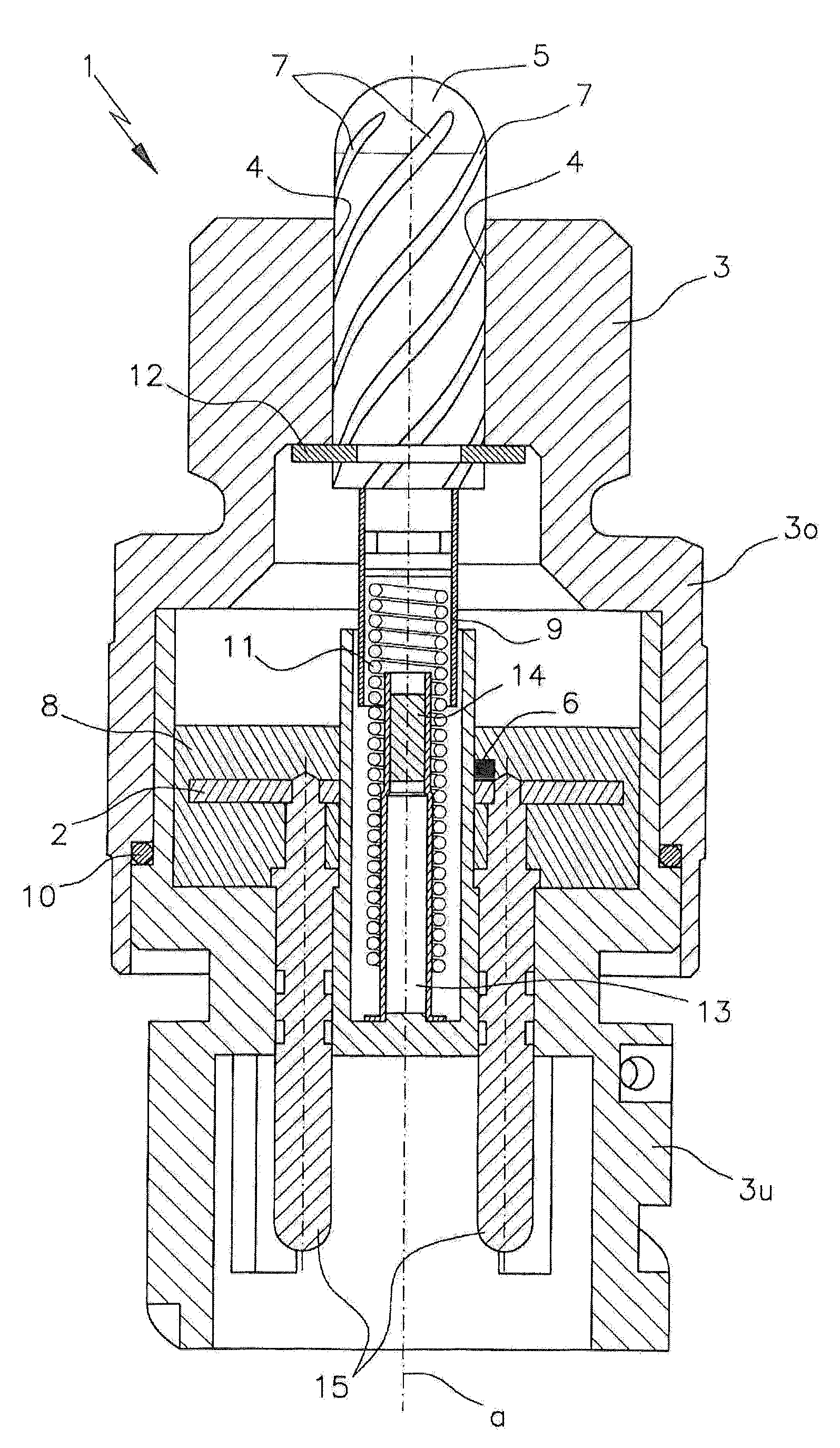
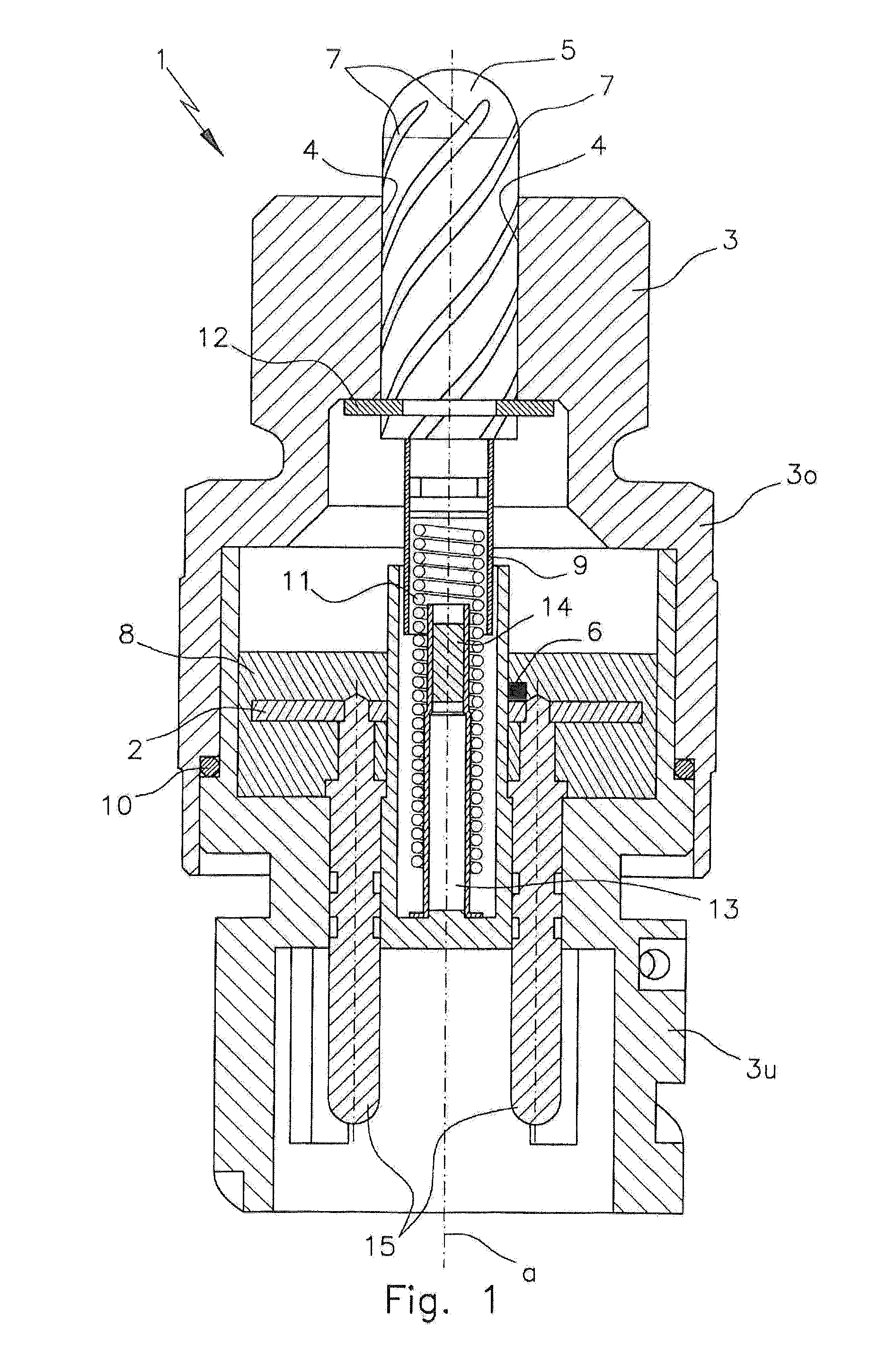
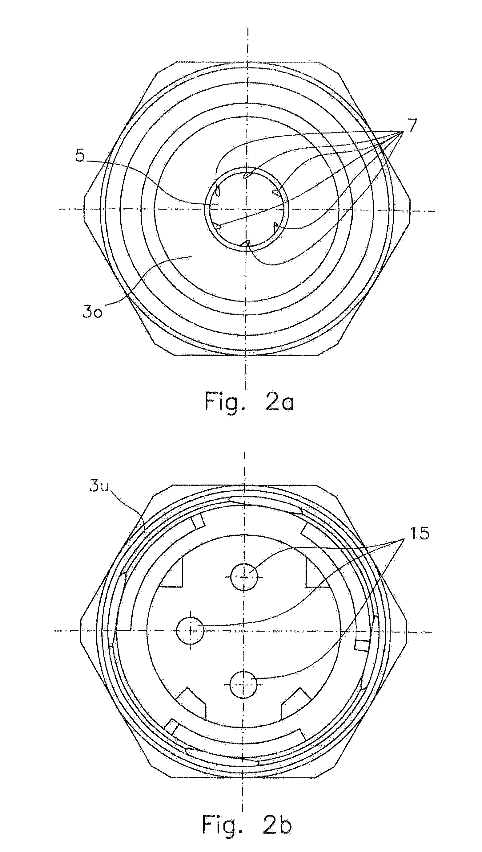
[0035]The exemplary embodiments of the plunger switch 1; 1′ according to the invention—which are depicted both schematically and in detail in the figures and show a plunger switch for use as a switch element in an electrical circuit 2—have a housing 3; 3′ and a plunger 5 that is able to move axially in a bore 4 of the housing 3; 3′ in the direction of a longitudinal axis a and when in an operating position in which it is depressed toward the housing 3; 3′, acts on an electronic sensor unit 6; 6′ situated in the housing 3; 3′, which in turn initiates a switching procedure in the electrical circuit 2 by means of electrical pulses.

[0036]According to the invention, the plunger switch 1; 1′ is distinguished from conventional switches by the fact that the plunger 5, in its axial plunging region into the bore 4 of the housing 3; 3′, is peripherally provided with at least one lubricating groove 7, which permits a lubricating fluid to travel into the axial plunging region between the plunger...


PUM


Abstract

A plunger switch for use as a switch element in an electrical circuit, has a housing and a plunger movable axially in a bore of the housing in the direction of a longitudinal axis and when in an operating position in which it is depressed toward the housing, acts on an electronic sensor unit situated in the housing, which in turn initiates a switching procedure in the electrical circuit by electrical pulses, and the plunger, in its axial plunging region into the bore of the housing, is peripherally provided with at least one lubricating groove, which permits a lubricating fluid to travel into the axial plunging region between the plunger and bore, and the electronic sensor unit is protected from a penetration of lubricating fluid.

Description

CROSS-REFERENCE TO RELATED APPLICATION[0001]The invention described and claimed hereinbelow is also described in German Patent Application DE 10 2010 033 014.0 filed on Jul. 31, 2010. This German Patent Application, whose subject matter is incorporated here by reference, provides the basis for a claim of priority of invention under 35 U.S.C. 119(a)-(d).BACKGROUND OF THE INVENTION[0002]The invention relates to a plunger switch for use as a switch element in an electrical circuit, having a housing and a plunger that is able to move axially in a bore of the housing in the direction of a longitudinal axis and when in an operating position in which it is depressed toward the housing, acts on an electronic sensor unit situated in the housing, which in turn initiates a switching procedure in the electrical circuit by means of electrical pulses.[0003]A plunger switch of this kind is known, for example, from EP 1 710 821 A1 or US 2007 / 0290642 A1.[0004]U.S. Pat. No. 4,481,806 A describes a pl...

Claims


Application Information

Patent Timeline
Patent Type & Authority Applications(United States)
IPC IPC(8): H01H9/00
CPCH01H3/62H01H36/00H01H13/06
Inventor WEIROWSKI-HERZ, ACHIMSTEIMLE, KARLHENGSTLER, ROLAND
Owner KISSLING ELEKTROTECHNIK GMBH & CO KG
Why Eureka
Try Eureka