Electronic device having solar cell antenna element and related methods

a technology of solar cell and antenna element, applied in the direction of resonant antenna, substantially flat resonant element, radiating element structure, etc., can solve the problems of cost of solar panel, difficult to implement on solar cell,

Active Publication Date: 2012-02-02
HARRIS CORP
View PDF3 Cites 12 Cited by
  • Summary
  • Abstract
  • Description
  • Claims
  • Application Information

AI Technical Summary

Benefits of technology

[0014]The drive shunt conductor may be coupled to the ground plane adjacent the coaxial antenna feed line. The electronic device may include an electrical power conductor coupled to the second power terminal. The ground plane may have an opening therein ad...

Problems solved by technology

This may be difficult to implement on a solar cell.
$11,729 per pound times 15 pounds per square...

Method used


Image

  • Electronic device having solar cell antenna element and related methods
  • Electronic device having solar cell antenna element and related methods
  • Electronic device having solar cell antenna element and related methods

Examples


Embodiment Construction

[0024]The present invention will now be described more fully hereinafter with reference to the accompanying drawings, in which preferred embodiments of the invention are shown. This invention may, however, be embodied in many different forms and should not be construed as limited to the embodiments set forth herein. Rather, these embodiments are provided so that this disclosure will be thorough and complete, and will fully convey the scope of the invention to those skilled in the art. Like numbers refer to like elements throughout, and prime notation is used to indicate similar elements in alternative embodiments.

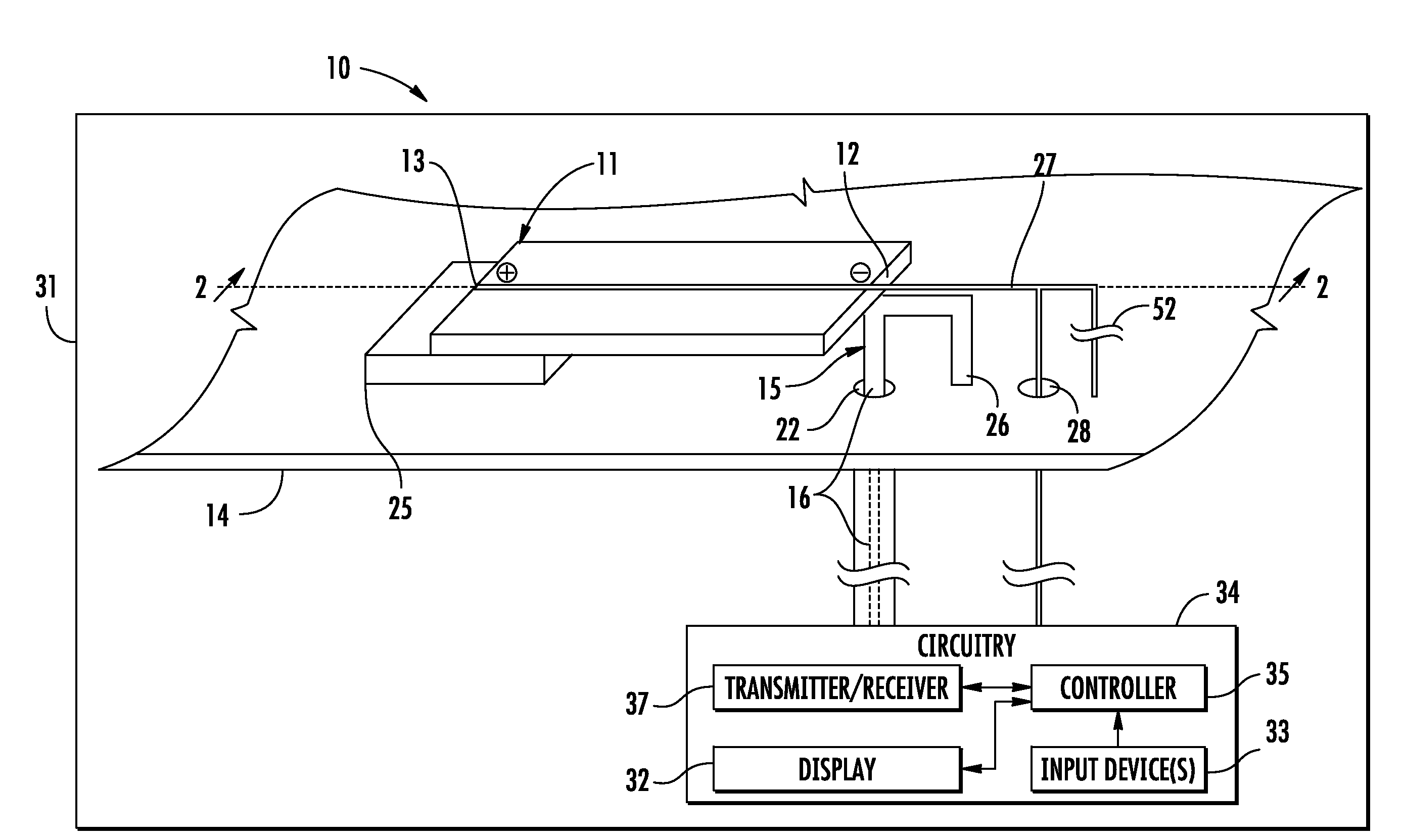
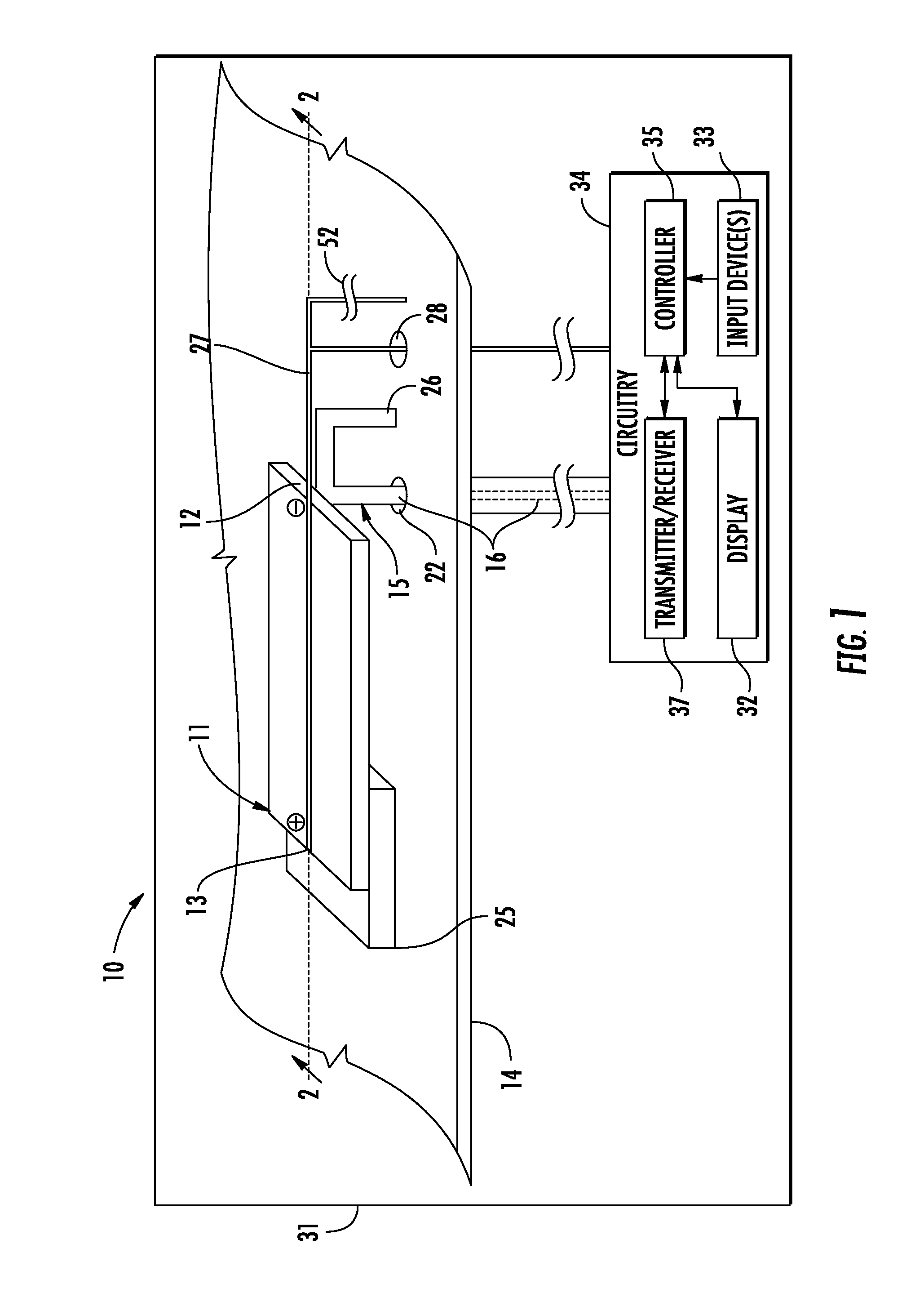
[0025]Referring initially to FIGS. 1-4, an electronic device 10 illustratively includes a housing 31. The electronic device also includes circuitry 34 carried by the housing 31. The circuitry 34 includes input devices 33 and a display 32. The circuitry 34 also includes a receiver and / or transmitter 37.

[0026]The circuitry 34 includes a controller 35 that is coupled to the di...


PUM


Abstract

An antenna may include a ground plane and a solar cell spaced above the ground plane. The solar cell may have first and second power output terminals. The antenna may include a coaxial antenna feed line including an inner conductor coupled to the first power output terminal, and an outer conductor coupled to the ground plane so that the solar cell also serves as a patch antenna element. The antenna may further include a drive shunt conductor extending between the first terminal and the ground plane.

Description

FIELD OF THE INVENTION[0001]The present invention relates to the field of electronic devices, and, more particularly, to electronic devices including solar cell antennas and related methods.BACKGROUND OF THE INVENTION[0002]A patch antenna is a common type of antenna and typically includes a single metal patch suspended over a ground plane. A patch antenna may have a length of approximately one-half wavelength of a desired frequency, for example. A patch antenna may be constructed on a dielectric substrate, and may include lithographic patterning used to fabricate printed circuit boards. A patch antenna typically requires an electrical tap into the patch body. This may be difficult to implement on a solar cell.[0003]Antennas are realized by the motion of electric currents on conductive shapes. Euclidian geometries may be preferred antenna shapes as they are known for increased performance. Canonical antenna types include the dipole and the loop, which use divergence and curl motions....

Claims


Application Information

Patent Timeline
IPC IPC(8): H01Q1/44
CPCH01L31/02008H01Q1/38Y02E10/50H01Q9/0407H01Q1/44
Inventor PARSCHE, FRANCIS EUGENE
Owner HARRIS CORP
Why Eureka
Try Eureka