Imaging apparatus

Inactive Publication Date: 2012-02-02
PANASONIC CORP
View PDF6 Cites 8 Cited by
  • Summary
  • Abstract
  • Description
  • Claims
  • Application Information

AI Technical Summary

Benefits of technology

[0010]In view of above problems, firstly, there is provided an imaging apparatus with the 3D conversion lens (dual lens adapter) is attached thereto that can prevent recording of a 3D image which is hard to be visually recognized by a user according to a change in ambient temperature. Secondly, there is provided an imaging apparatus which can prevent an abnormal image from being recorded even when the 3D conversion lens adapter is attached in a time of power ON. Thirdly, there is provided an imaging apparatus that can prevent incapability of user's satisfactorily recognizing a 3D image when the imaging apparatus to which the 3D conversion lens is attached performs electronic zoom.
[0014]In the imaging apparatus according to the first aspect, when the 3D conversion lens is attached to the apparatus, a zoom lens is moved to a predetermined position. At this time, the predetermined position is determined based on ambient temperature of the apparatus. As a result, in a state that the 3D conversion lens is attached to the apparatus, the zoom lens can be moved to a position according to the ambient temperature of the apparatus. For example, the zoom lens may be moved so that a reference plane position with respect to the distance between the 3D conversion lenses is not changed according to the temperature change. As a result, the reference plane position is fixed regardless of the ambient temperature. That is to say, a projecting amount (retrojecting amount) of the 3D image is prevented from changing due to the temperature change. Therefore, satisfactory 3D images can be provided to the user.

Problems solved by technology

For this reason, when the 3D conversion lens (a dual lens adapter) is attached at a time of power ON, an abnormal image may be recorded.
As a result, the captured 3D image might be a 3D image that provides bad visibility to a user.
For this reason, the projecting amount or the retrojecting amount of a 3D image becomes extremely large due to an electronic zoom operating amount, and thus the user cannot visually recognize the 3D image satisfactorily.
As a result, even when the 3D conversion lens is attached in the time of power ON, abnormal images are not presented to the user.

Method used


Image

  • Imaging apparatus
  • Imaging apparatus
  • Imaging apparatus

Examples


first embodiment

1. First Embodiment

[0033]A first embodiment will be described with reference to the drawings.

1-1. Outline

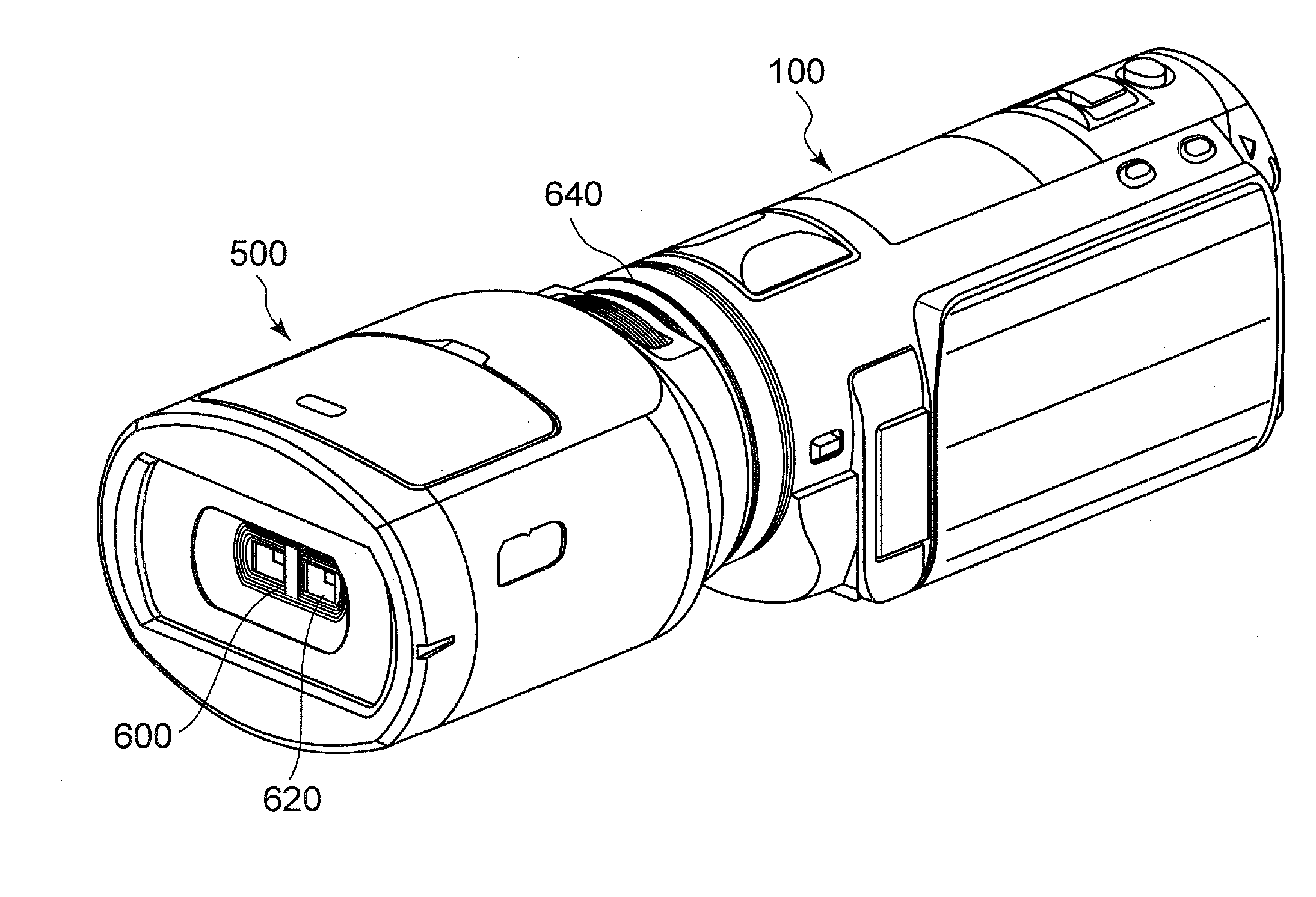
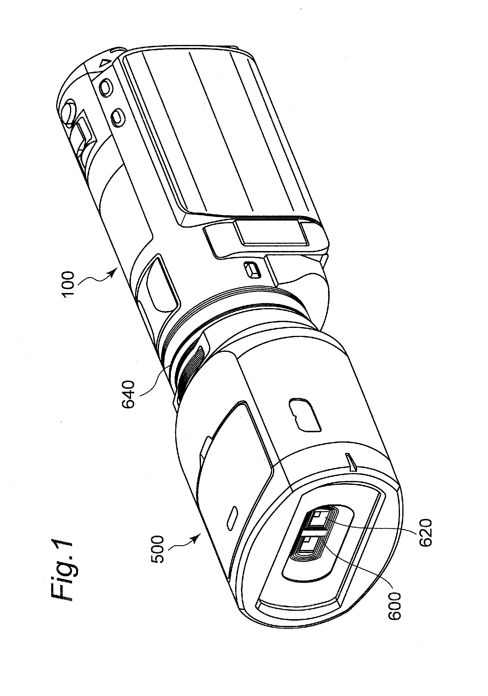
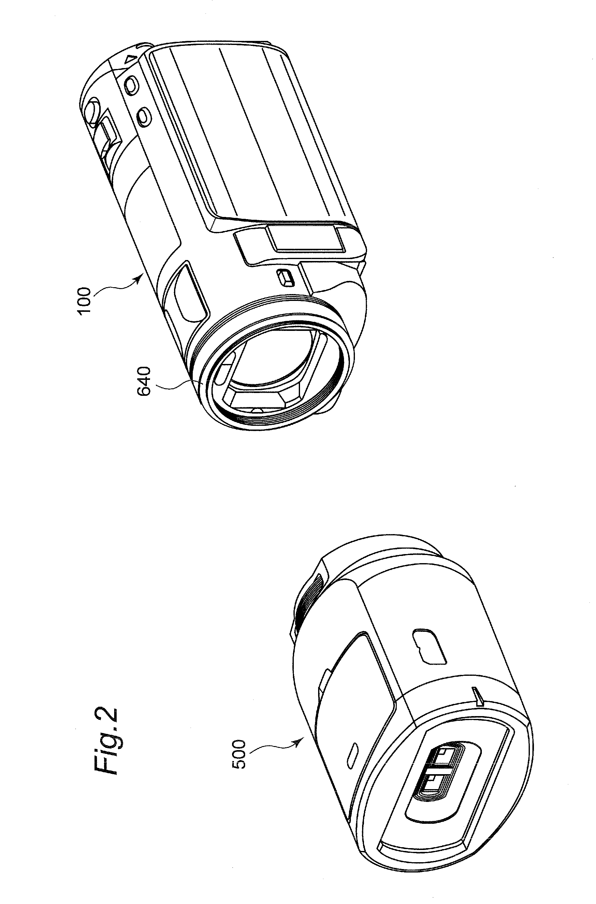
[0034]An outline of a digital video camera 100 according to the first embodiment will be described with reference to FIGS. 1 to 3. FIG. 1 is a perspective view illustrating a state that a 3D conversion lens 500 is attached to the digital video camera 100. FIG. 2 is a perspective view illustrating a state that the 3D conversion lens 500 is detached from the digital video camera 100.

[0035]As shown in FIG. 1, the digital video camera 100 has a mounting section 640 for mounting the 3D conversion lens 500. The mounting section 640 has a female screw inside. On the other hand, the 3D conversion lens 500 has a male screw that is engaged with the female screw provided to the mounting section 640. A user allows the male screw of the 3D conversion lens 500 to be engaged with the female screw of the mounting section 640, so that the 3D conversion lens 500 can be attached to the digital vide...

second embodiment

2. Second Embodiment

[0068]A second embodiment will be described with reference to the drawings. Description about the same configuration as that of the digital video camera 100 according to the first embodiment will be omitted.

[0069]When the 3D conversion lens 500 is attached to the digital video camera 100 according to the second embodiment, as the initial setting in the 3D mode, the zoom lens is moved to the side of the telephoto end. However, differently from the first embodiment, the zoom lens is moved not to one point of the telephoto end but to a predetermined position near the telephoto end according to an ambient temperature.

[0070]A problem of the second embodiment will be first described. The distance between the lenses in the 3D conversion lens changes according to the expansion / contraction of the supporting member for supporting the lenses including the optical system or the like according to the change in the ambient temperature. When the distance between the lenses chan...

third embodiment

3. Third Embodiment

[0082]A third embodiment will be described below with reference to the drawings. Description about the same configuration as that of the digital video camera 100 in the first embodiment will be omitted.

[0083]The digital video camera 100 according to the third embodiment has an electronic zoom function. The electronic zoom is not zoom by means of the optical system, but zoom for electronically processing an image imaged on the CCD image sensor 180 so as to enlarge the image. In the third embodiment, when the electronic zoom is performed by an operating member 250 and the zoom lever 260, it is performed by an image processor 190 according to an instruction of the controller 210.

[0084]When the electronic zoom for enlarging an L image and an R image to a double size (length) is performed, the parallax amount therebetween is doubled. That is to say, the projecting amount and the retrojecting amount become double, and thus the image might be very less-visible for the us...


PUM


Abstract

An imaging apparatus can connect a 3D conversion lens. The 3D conversion lens has an optical system capable of collecting light for forming a left-eye image and light for forming a right-eye image. The imaging apparatus has an imaging device, a zoom lens operable to change a magnification of an image to be imaged on the imaging device, a driver operable to drive the zoom lens, a temperature detector operable to detect an ambient temperature of the apparatus, an attachment detector operable to detect whether the 3D conversion lens is attached to the apparatus, and a controller operable to control the driver to cause the zoom lens to move to a predetermined position, when the attachment detector detects that the 3D conversion lens is attached to the apparatus. The controller determines the predetermined position based on a detected result of the temperature detector.

Description

BACKGROUND[0001]1. Technical Field[0002]The technical field relates to an imaging apparatus. The technical field particularly relates to the imaging apparatus to / from which a 3D conversion lens can be attached / detached.[0003]2. Related Art[0004]Japanese Patent Application JP-2001-222083-A discloses an imaging apparatus. A 3D conversion lens (dual lens adapter) can be attached to the imaging apparatus. The imaging apparatus to which the 3D conversion lens is attached can image a three-dimensional stereoscopic image (3D image). When a power of the imaging apparatus is ON with the 3D conversion lens being attached thereto, the imaging apparatus changes a focal position of a zoom lens to a wide end.[0005]With this arrangement, this 3D conversion lens does not have to support all zoom regions of the imaging apparatus.SUMMARY[0006]However, for the imaging apparatus disclosed in JP-2001-222083-A, it is assumed that the 3D conversion lens is attached to the imaging apparatus at a time of po...

Claims


Application Information

Patent Timeline
IPC IPC(8): H04N13/02
CPCH04N13/0296H04N13/0217H04N13/296H04N13/218
Inventor KAKIUCHI, KENJITABATA, KAZUMASAYABUKI, TAKANORIMURAKAMI, MASAHIROMATSUI, ATSUSHI
Owner PANASONIC CORP
Why Eureka
Try Eureka