Optical arrangement for tracking detector

a tracking detector and optical arrangement technology, applied in the direction of optical radiation measurement, instruments for comonautical navigation, instruments, etc., can solve the problem of exacerbated detection errors related to light level variations at the sensor apertur

Inactive Publication Date: 2012-02-02
LOCKHEED MARTIN CORP
View PDF4 Cites 0 Cited by
  • Summary
  • Abstract
  • Description
  • Claims
  • Application Information

AI Technical Summary

Benefits of technology

[0005]Embodiments of a laser spot tracker discussed herein may allow an image spot to be tuned and shaped to a detector with minimal sensitivity to turbulence or external window contamination. An embodiment of a turbulence-insensitive laser-spot tracker may include a filter that filters incoming radiation, and a beam splitter that splits the filtered radiation into multiple beams or beam sets.
[0008]After deviation and reflection, the beams may be focused by a lens onto a detector for tracking. Such an arrangement may allow for the elimination of a defocus device commonly found in laser spot trackers. Defocusing spreads the entire detected laser signal across the plane of the detector to improve detection sensitivity and servo tracking ability. Defocusing, however, also exacerbates detection errors related to light level variations at the sensor aperture caused by atmospheric effects such as turbulence, fog, or window contamination. The defocus creates a small image of the aperture on the surface of the detector which changes its centroid location as the intensity distribution changes on the sensor aperture. By not having to defocus the beam but instead generating dual opposing laser spot images for each point on the aperture, turbulence effects may be reduced because the image centroid location doesn't change.

Problems solved by technology

Defocusing, however, also exacerbates detection errors related to light level variations at the sensor aperture caused by atmospheric effects such as turbulence, fog, or window contamination.

Method used


Image

  • Optical arrangement for tracking detector
  • Optical arrangement for tracking detector
  • Optical arrangement for tracking detector

Examples


Embodiment Construction

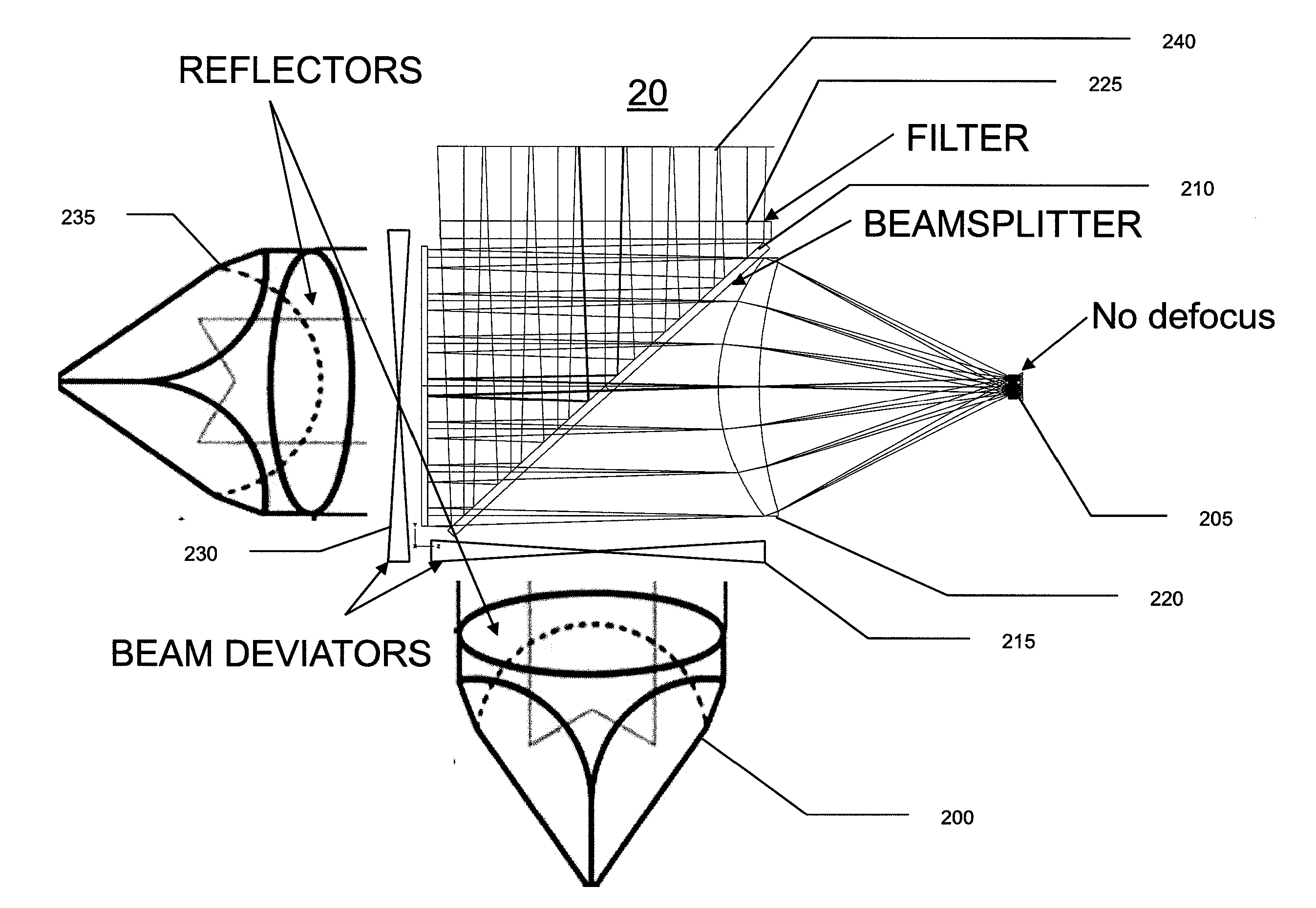
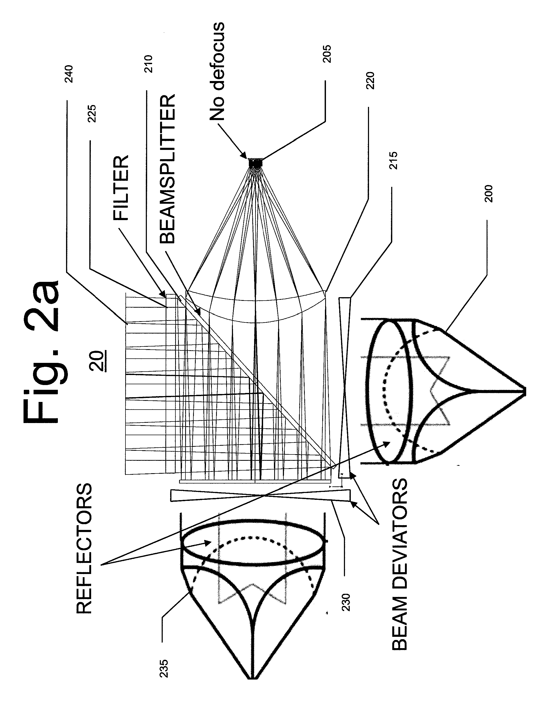
[0022]The present invention comprises a method and apparatus for the reduction and mitigation of detection errors and inaccuracies in a laser tracking detection system caused by turbulence and other atmospheric conditions.

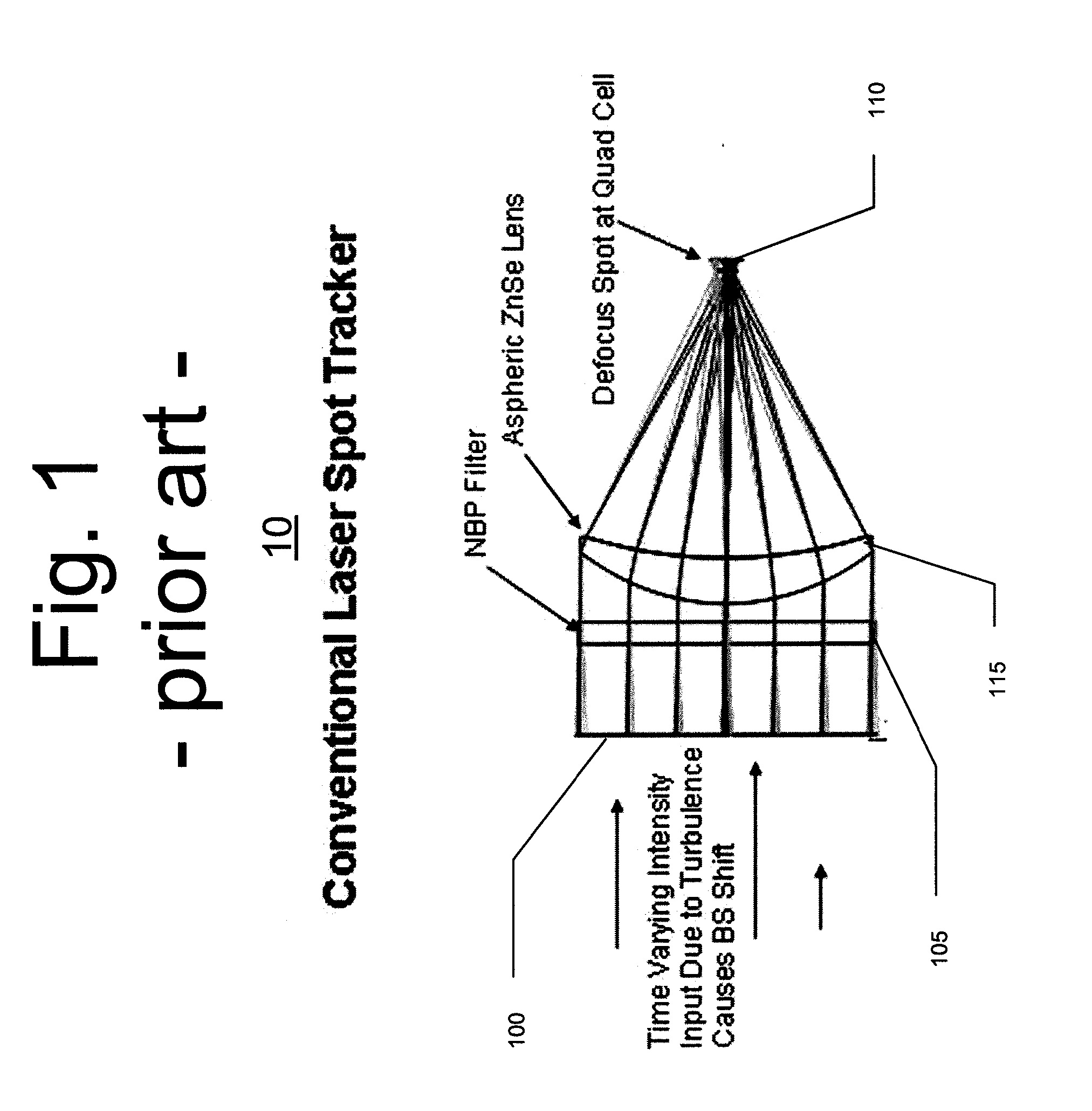
[0023]In a conventional laser spot tracker as shown in FIG. 1, incoming radiation is admitted through an aperture 100 at the front of the tracker 10. The radiation then passes through a narrow band-pass (NBP) filter 105 that removes all but the desired wavebands of laser radiation. The filtered radiation is then focused with a lens 115 onto an intermediate focal plane. The quad-cell detector 110 is located behind the best optical focus so that the defocused image blur fills most of the quad cell array. The effect of this de-focus is to spread the laser spot image across the array to improve detector sensitivity, thereby allowing for more accurate gimbal servo pointing and therefore improved laser spot tracking. An undesirable side-effect of this de-focus, however, ...


PUM


Abstract

A system and method of reducing turbulence sensitivity in a laser spot detector. Embodiments may include using beam splitters, reflectors, and beam deviators. The reflectors may be trihedral reflectors and the beam deviators may be segmented wedge plates having predetermined physical angles and angle directions in each wedge segment designed to produce opposing blurs for each segment of the aperture. A predetermined blur introduced into each line of sight eliminates the need for de-focus, thereby mitigating effects such as centroid shift caused by turbulence or dirty / damaged sensor apertures.

Description

CROSS REFERENCE TO RELATED APPLICATIONS[0001]This application is a Divisional of copending application Ser. No. 12 / 479,417 filed on Jun. 5, 2009, which claims priority to Application No. 61 / 059,522 filed on Jun. 6, 2008. The entire contents of all of the above applications is hereby incorporated by reference.BACKGROUND OF THE INVENTION[0002]A Laser Spot Tracker (LST) for an airborne or a ground system usually employs a proportional quad cell detection mode where all four quadrants of the detection cell have continuous illumination. Some types of laser spot trackers using a four-quadrant detection cell require a relatively large image spot diameter in order to operate in the proportional mode—that is in order to determine an energy centroid in the laser spot and orient themselves accordingly.[0003]When a large spot diameter is achieved with a beam spoiler or similar de-focusing device located in the laser spot tracker, the energy centroid of the detected signal changes position on th...

Claims


Application Information

Patent Timeline
Patent Type & Authority Applications(United States)
IPC IPC(8): G01B11/26
CPCF41G7/226F41G7/2293G02B27/144G01S17/66G01S7/4816
Inventor GUNDERSON, JOHN
Owner LOCKHEED MARTIN CORP
Why Eureka
Try Eureka