Vibration method to detect onset of gas lock

a vibration method and gas lock technology, applied in the direction of piston pumps, instruments, borehole/well accessories, etc., can solve the problems of gas lock onset, head degradation and gas lock, premature failure,

Active Publication Date: 2012-02-02
BAKER HUGHES INC
View PDF2 Cites 38 Cited by
  • Summary
  • Abstract
  • Description
  • Claims
  • Application Information

AI Technical Summary

Benefits of technology

[0013]An advantage of the disclosed embodiments is that they provide a method for detecting gas lock that allows operators to determine gas lock onset prior to manifestation of the

Problems solved by technology

ESPs are designed to handle liquid and will suffer from head degradation and gas locking in the presence of a high percentage of free gas.
Despite use of gas separators, gas lock may occur when an ESP ingests sufficient gas so that the ESP can no longer pump fluid to the surface due to, for example, large gas bubbles in the well fluid.
This occurs despite the use of gas separ

Method used


Image

  • Vibration method to detect onset of gas lock
  • Vibration method to detect onset of gas lock
  • Vibration method to detect onset of gas lock

Examples


Embodiment Construction

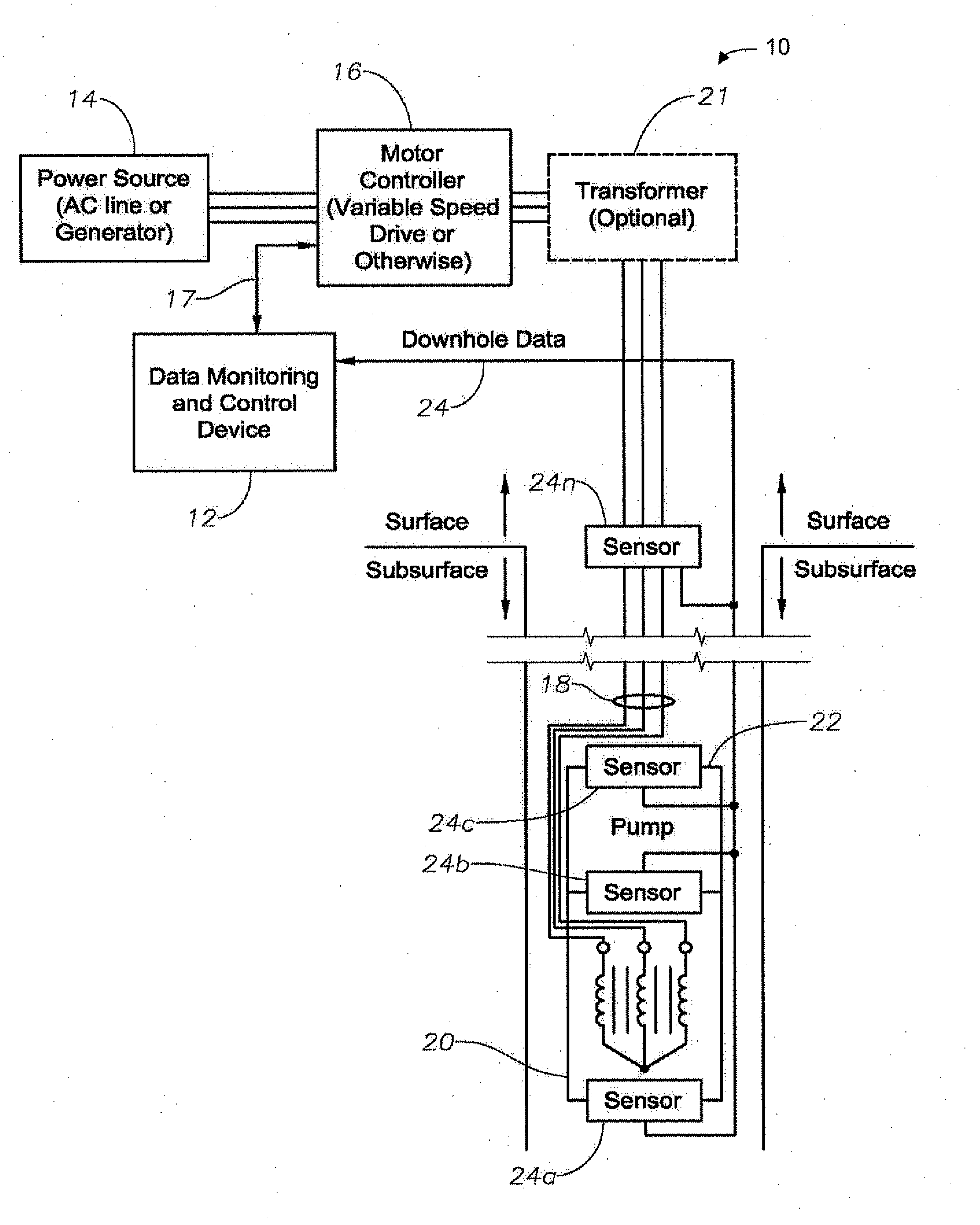
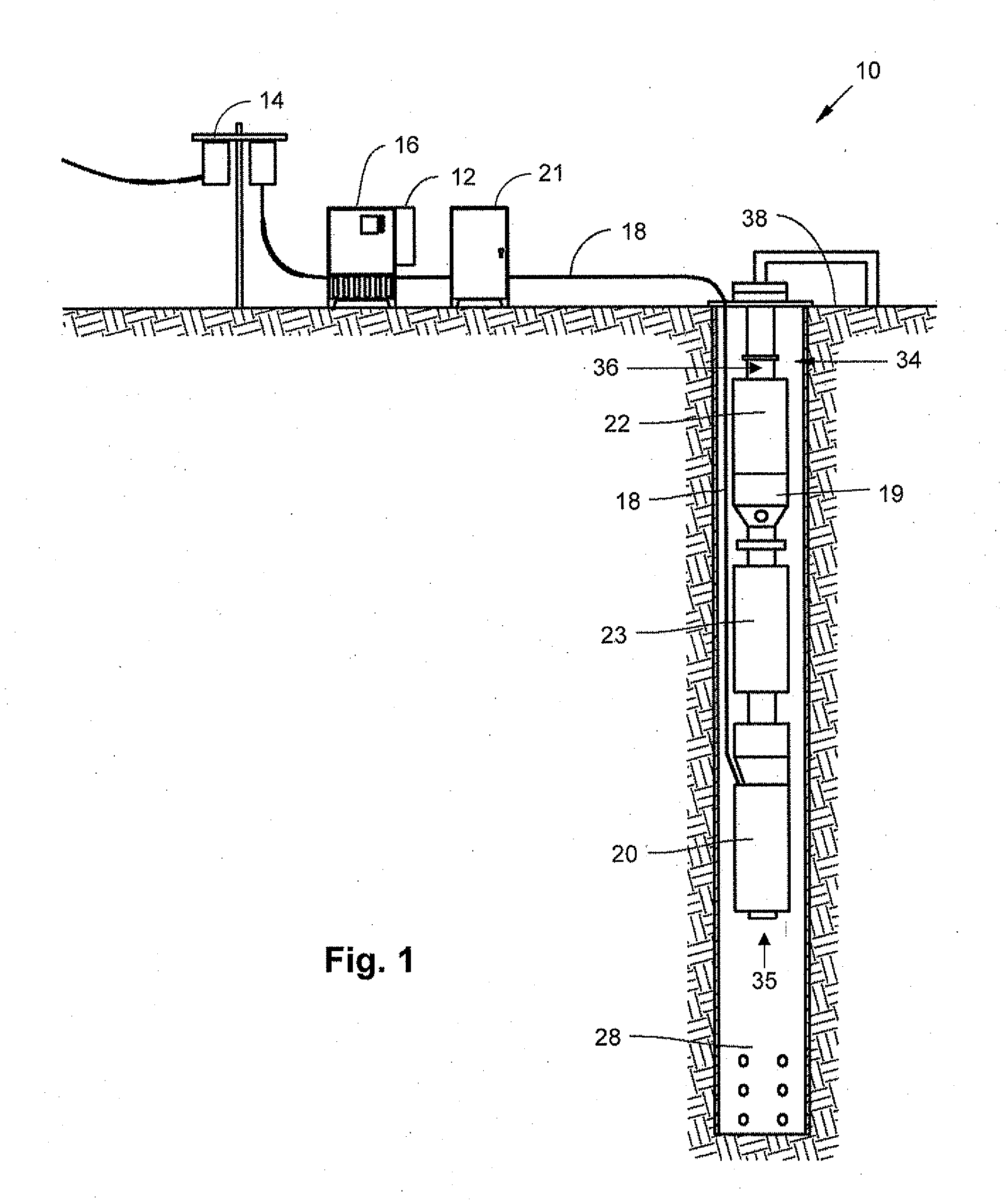
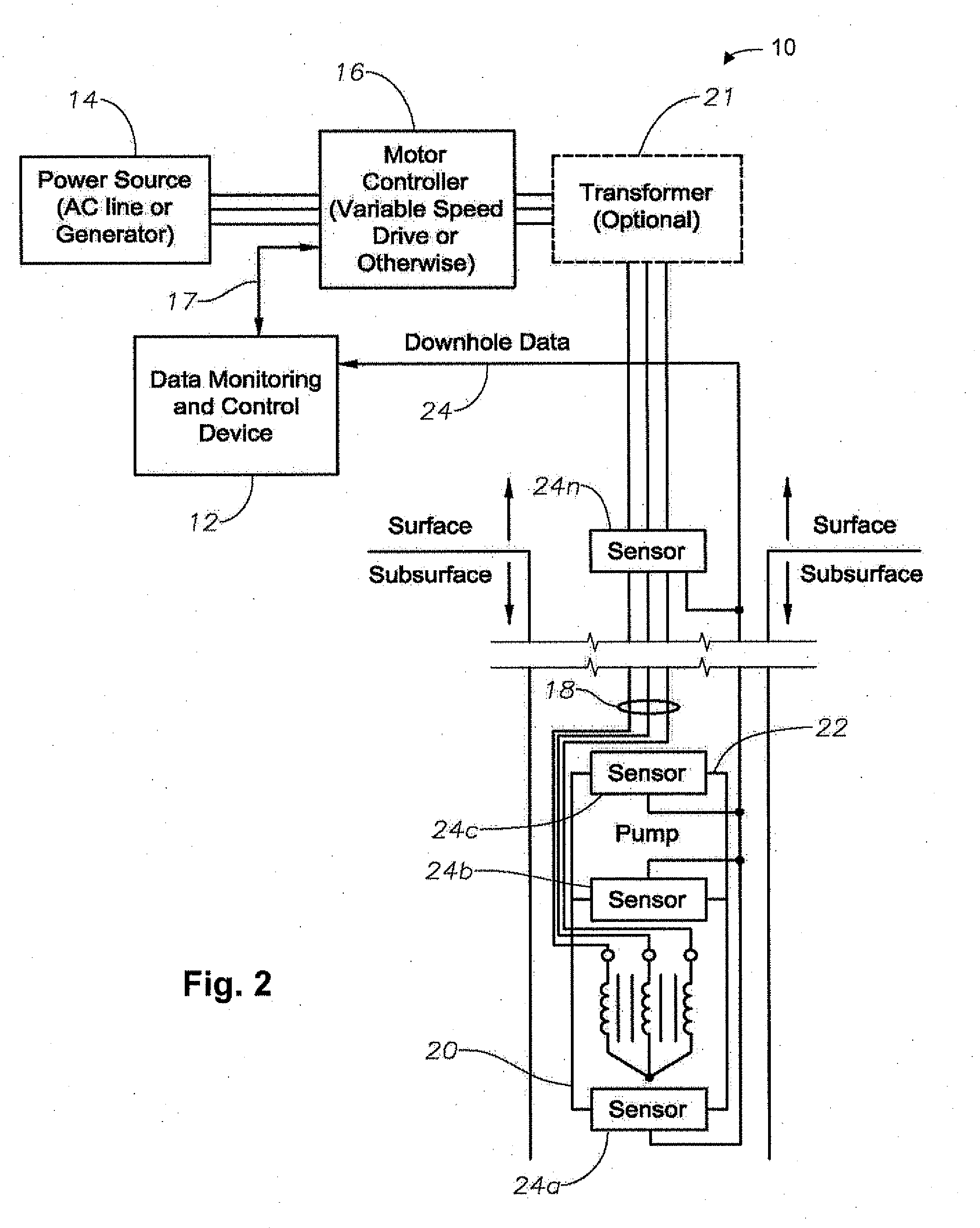
[0023]The present invention will now be described more fully hereinafter with reference to the accompanying drawings which illustrate embodiments of the invention. This invention may, however, be embodied in many different forms and should not be construed as limited to the illustrated embodiments set forth herein. Rather, these embodiments are provided so that this disclosure will be thorough and complete, and will fully convey the scope of the invention to those skilled in the art. Like numbers refer to like elements throughout, and the prime notation, if used, indicates similar elements in alternative embodiments.

[0024]In the following discussion, numerous specific details are set forth to provide a thorough understanding of the present invention. However, it will be obvious to those skilled in the art that the present invention may be practiced without such specific details. Additionally, for the most part, details concerning ESP operation, construction, and the like have been o...


PUM


Abstract

Vibration of an electric submersible pump assembly is monitored to produce a vibration spectrum. The vibration spectrum is compared to a known vibration signature for a pump condition that precedes gas lock. The pump condition is at least one of an impeller rotating stall condition, a diffuser stall condition, a pre-surge condition, and percentage of free gas within the wellbore fluid. Operation of the pump is then adjusted in response to the similarity of the vibration spectrum to the vibration signature for the pump condition to prevent impending gas lock.

Description

[0001]This application claims priority to and the benefit of co-pending U.S. Provisional Application No. 61 / 521,791, by Forsberg et al., filed on Aug. 10, 2011, entitled “Vibration Method to Detect Onset of Gas Lock,” which application is incorporated herein by reference.[0002]This application is a continuation in part of U.S. Utility patent application Ser. No. 12 / 486,121, entitled “Device and Method for Gas Lock Detection in an Electrical Submersible Pump Assembly” by Allen et al., filed on Jun. 17, 2009, published as U.S. Patent Application Publication No. 2009 / 0250210, on Oct. 8, 2009, attorney docket number CNT4-48189, currently pending before the United States Patent and Trademark Office, which is a continuation in part of U.S. Utility patent application Ser. No. 12 / 144,092, by Leuthen et al., titled “Device, Method and Program Product to Automatically Detect and Break Gas Locks in an ESP” filed on Jun. 23, 2008, which claims priority to U.S. Provisional Patent Application No....

Claims


Application Information

Patent Timeline
IPC IPC(8): E21B47/008G01N29/02
CPCE21B43/128E21B47/0007F04D9/001F04D15/0209F04D15/0066F04D15/0088F04D13/10E21B47/008
Inventor FORSBERG, MICHAEL A.SHETH, KETANKUMAR K.WILSON, BROWN LYLEBROWN, DONN J.ZHU, DEHAO DAVID
Owner BAKER HUGHES INC
Why Eureka
Try Eureka