Apparatus for Identifying Femoral Head Center

a femoral head and center technology, applied in the field of femoral head center identifying apparatus, can solve the problems of inability to determine whether or not the bone resection block is in the correct position, the technique has difficulty in achieving high accuracy in bone resection, and the increase in surgical costs, etc., to achieve the effect of accurate identifying the position of the femoral head center and inexpensive configuration

Inactive Publication Date: 2012-02-02
KANEKASU KOICHI
View PDF13 Cites 12 Cited by
  • Summary
  • Abstract
  • Description
  • Claims
  • Application Information

AI Technical Summary

Benefits of technology

[0008]The invention is directed to overcoming the foregoing problems and therefore a primary object of the invention is to provide a femoral head center identifying apparatus capable of accurately identifying the position of a femoral head center even during surgery, with an inexpensive configuration.
[0012]In this configuration, the distance from the pivotal shaft to the marker in a direction parallel to the frontal plane is equal to the distance from the distal end of the femur to the femoral head center which distance has been measured preliminarily, and the pivotal shaft is placed at the distal end of the femur. Therefore, when a circular arc is depicted on the marking plate with the marker by pivoting the pivotal arm, this circular arc passes through a point opposed to the femoral head center. Hence, when the hip joint is adducted or abducted thereby to position the femur in a first position and a second position which are distant from each other and a first circular arc and a second circular arc are depicted on the marking plate while the femur being located in these positions, the first and second circular arcs intersect each other at the point opposed to the femoral head center. With this intersection point, the position of the femoral head center can be identified within the plane parallel to the frontal plane. According to this configuration, the position of the femoral head center can be accurately identified within the plane parallel to the frontal plane, during total knee replacement surgery. In addition, since there is no need to employ a navigation system, surgery expense can be reduced and possible damage to the femur (e.g., damage caused by the pins used for securing the indicator section) can be avoided.
[0014]In this configuration, the distance from the pivotal shaft to the marker can be adjusted in accordance with the distance from the distal end of the femur to the femoral head center. This enables the femoral head center identifying apparatus to be equally applicable to a plurality of patients having different femur lengths.
[0016]Generally, the patients undergoing total knee replacement have damage in the medial and lateral condyles of the distal end of the femur and their medial and lateral condyles are distorted in shape depending upon the degree of damage. In contrast with this, the deepest part of the intercondylar region at the distal end of the femur is not affected by wear and bone destruction caused by load and is therefore unlikely to be deformed in shape. In this configuration, since the tubular stem section is secured at the deepest part of the intercondylar region at the distal end of the femur, stably secured state is attained.
[0024]In this configuration, since the marking plate can be dismounted after identification of the position of the femoral head center, it is possible to prevent the marking plate from becoming an obstacle to the surgery.
[0028]In this configuration, the guide hole can be positioned in place with respect to the block fastening pin by positioning the marker such that it is opposed to the femoral head center. In consequence, the bone resection block can be accurately disposed in place by inserting the block fastening pin into a proper position of the distal end of the femur through the guide hole and securing the bone resection block with this block fastening pin.

Problems solved by technology

This navigation system however has a problem that it incurs enormous development costs, resulting in a considerable increase in surgical expense.
However, this technique has difficulty in achieving a high accuracy in bone resection, because the bone resection block is blindly mounted on the distal end of the femur without checking the position of the femoral head center.
Therefore, it cannot be determined whether or not the bone resection block is in a correct position, based on the position of the femoral head center.

Method used


Image

  • Apparatus for Identifying Femoral Head Center
  • Apparatus for Identifying Femoral Head Center
  • Apparatus for Identifying Femoral Head Center

Examples


first embodiment

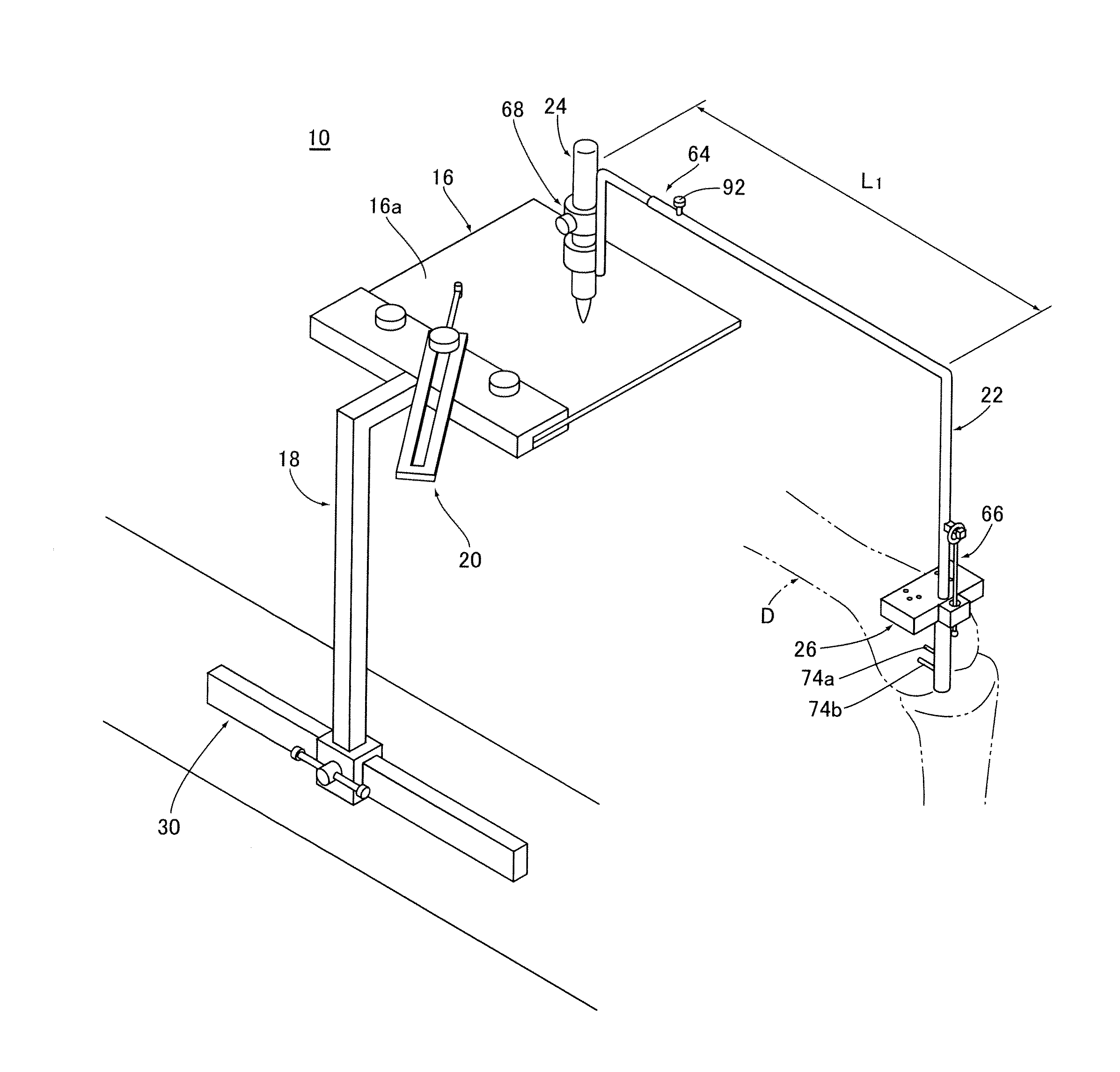
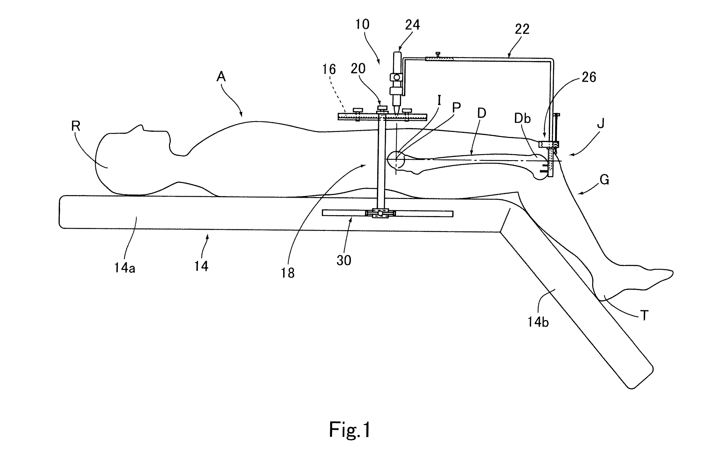
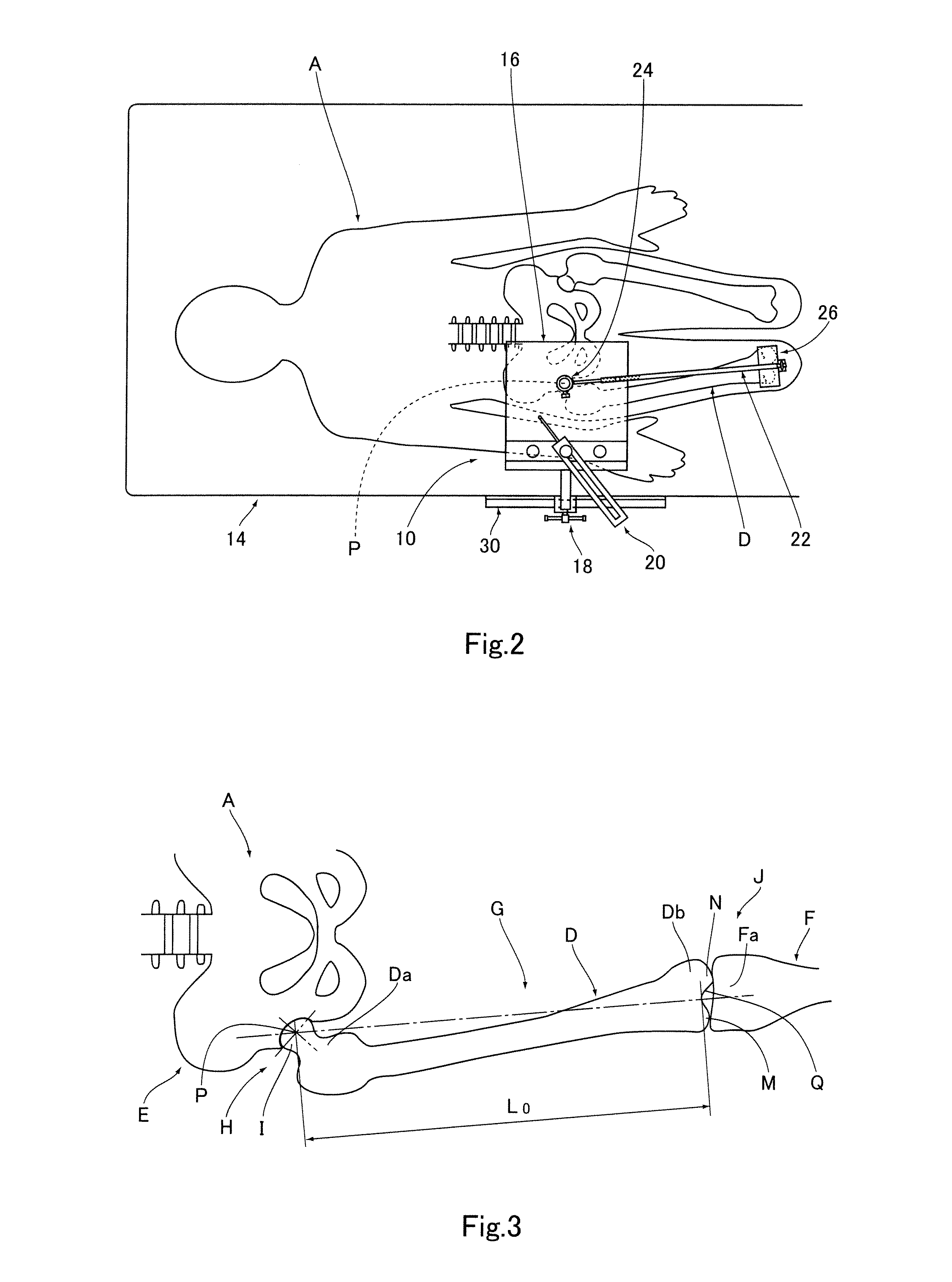
[0051]FIGS. 1 and 2 are a front view and plan view, respectively, showing a state where the femoral head center identifying apparatus 10 of the first embodiment is used in total knee replacement surgery. FIG. 4 is a perspective view showing the whole configuration of the femoral head center identifying apparatus 10.

[0052]As illustrated in FIGS. 1, 2 and 4, the femoral head center identifying apparatus 10 has a surgical table 14; a marking plate 16, a plate supporting section 18 and an indicator section 20 which are directly or indirectly attached to the surgical table 14; and a pivotal arm 22, a marker 24 and a pin guide 26 which are directly or indirectly attached to the femur D of the patient A.

Structure of Surgical Table

[0053]As illustrated in FIGS. 1 and 2, the surgical table 14 is for supporting the body of the patient A such that the frontal plane becomes horizontal and includes a first table 14a for supporting a region that extends from a knee joint J to a head R and a second...

second embodiment

[0086]FIG. 16 is a perspective view showing a configuration of a level indicator 142 provided in a femoral head center identifying apparatus 140 according to the second embodiment.

[0087]As shown in FIG. 16, in the femoral head center identifying apparatus 140 of the second embodiment, the level indicator 142 has a weight 144, a thread 146, a mounting section 148 and a plate 150, and the mounting section 148 and the plate 150 are integral with the arm section 62. In a position above the plate 150, the weight 144 is attached to the mounting section 148 through the thread 146 so as to suspend therefrom. A cross line 150a and a plurality of concentric circles 150b having different diameters are depicted on the top surface of the plate 150. When the pivotal shaft 76 is oriented in a vertical direction (i.e., a direction perpendicular to the frontal plane), the weight 144 is located in the center of the cross line 150a and the plurality of concentric circles 150b. Therefore, the direction...


PUM


Abstract

An apparatus for identifying, during total knee replacement surgery, a position of a center of a femoral head of a patient within a plane parallel to a frontal plane, comprises a marking plate placed to cover, in a direction perpendicular to the frontal plane, a site where the femoral head center of the patient's body is located; a pivotal arm having a pivotal shaft arranged to extend in a direction perpendicular to the frontal plane; and a marker attached to the pivotal arm, for depicting a circular arc on the marking plate according to rotation of the pivotal arm; the pivotal shaft being placed at a distal end of a femur of the patient, a distance from the pivotal shaft to the marker in a direction parallel to the frontal plane being equal to a preliminarily measured distance from the distal end of the femur to the femoral head center.

Description

BACKGROUND OF THE INVENTION[0001]1. Field of the Invention[0002]The invention relates to a femoral head center identifying apparatus for identifying the position of a femoral head center within a plane parallel to a frontal plane during total knee replacement surgery.[0003]2. Description of Related Art[0004]Generally speaking, when viewing an X-ray image (frontal plane image) of the anterior surface of a lower extremity, the weight bearing line of the human body conceivably passes through the central region of the knee joint, if the angle of intersection between the functional axis of the anterior surface of the femur which axis connects the femoral head center to the knee joint center, and the functional axis of the anterior surface of the os cruris which axis connects the knee joint center to the talus center (this angle is hereinafter referred to as “lower extremity alignment angle”) is zero degree. Therefore, such a lower extremity alignment is regarded as an ideal alignment.[00...

Claims


Application Information

Patent Timeline
Patent Type & Authority Applications(United States)
IPC IPC(8): A61B17/56
CPCA61B17/15A61B19/46A61B2019/469A61F2002/4668A61B2019/545A61F2/4657A61F2002/4658A61B2019/5437A61B90/06A61B2090/069A61B2090/3937A61B2090/395
Inventor KANEKASU, KOICHI
Owner KANEKASU KOICHI
Why Eureka
Try Eureka