System and method for identifying regions of distinct wind flow

a technology of wind flow and region, applied in the direction of meteorology, instruments, measurement devices, etc., can solve the problems of wind turbines placed within recirculation zones being subject to greater wear and tear

Inactive Publication Date: 2012-02-02
GENERAL ELECTRIC CO
View PDF1 Cites 11 Cited by
  • Summary
  • Abstract
  • Description
  • Claims
  • Application Information

AI Technical Summary

Benefits of technology

[0014]Another exemplary embodiment of the present disclosure is directed to a system for determining areas of distinct wind flow for a proposed wind power plant site. The system includes at least one processing device and at least one memory. The memory includes computer-readable instructions for execution by the at least one processing device to control the at least one processing device to: obtain wind velocity field data for a region in the proposed wind power plant site; identify an area of distinct wind flow based at least in part on the wind velocity field data; and map the area of distinct wind flow in the region.

Problems solved by technology

Not all locations within the geographic boundaries of a proposed wind farm are suitable for placement of a wind turbine.
Wind turbines placed within a recirculation zone can be subject to greater wear and tear due to the varying wind velocities and turbulence in the recirculation zone.
This typically involves a degree of guessing which can result in inconsistent results.

Method used


Image

  • System and method for identifying regions of distinct wind flow
  • System and method for identifying regions of distinct wind flow
  • System and method for identifying regions of distinct wind flow

Examples


Embodiment Construction

[0027]Reference now will be made in detail to embodiments of the invention, one or more examples of which are illustrated in the drawings. Each example is provided by way of explanation of the invention, not limitation of the invention. In fact, it will be apparent to those skilled in the art that various modifications and variations can be made in the present invention without departing from the scope or spirit of the invention. For instance, features illustrated or described as part of one embodiment can be used with another embodiment to yield a still further embodiment. Thus, it is intended that the present invention covers such modifications and variations as come within the scope of the appended claims and their equivalents.

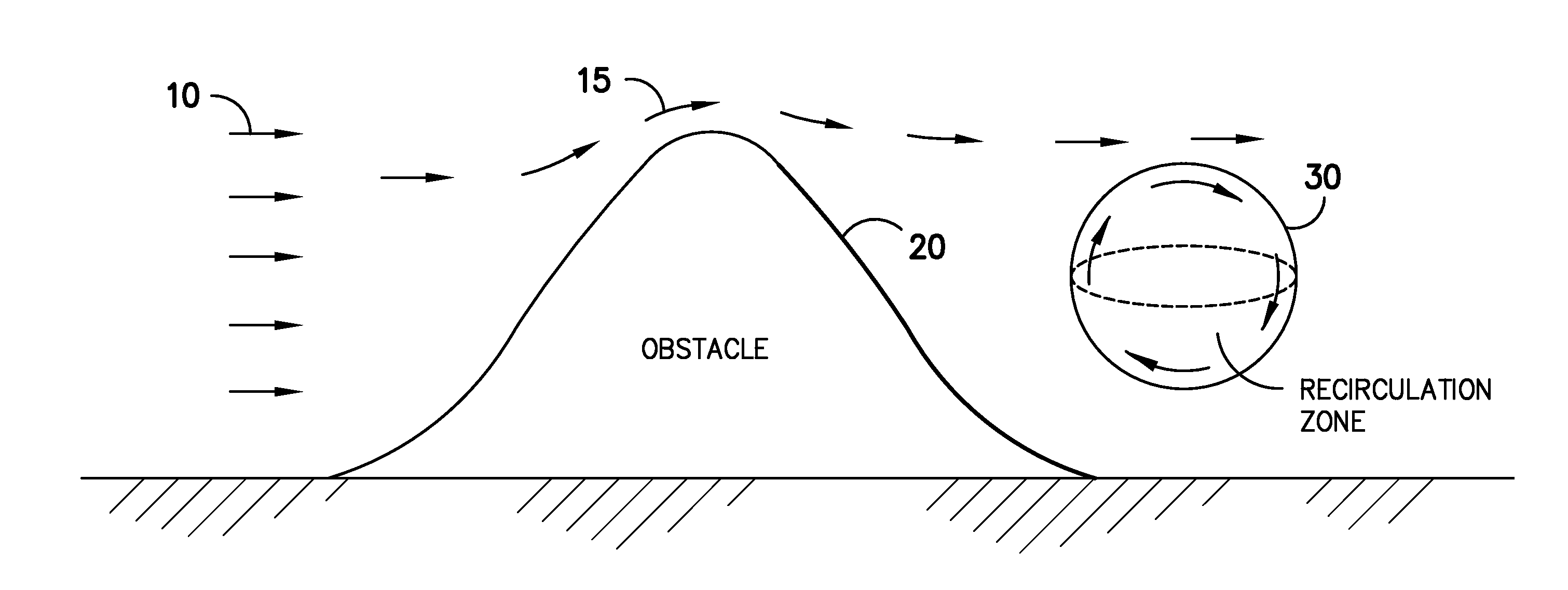
[0028]Generally, the present disclosure is directed to systems and methods for automatically identifying areas of distinct wind flow from wind velocity field data. The areas of distinct wind flow can be automatically identified using a fluid dynamic computa...


PUM


Abstract

Systems and methods for detecting areas of distinct wind flow in a region of a wind farm are disclosed. Areas of distinct flow can be identified by a computing tool based at least in part on wind velocity field data. For instance, using wind velocity field data, a finite-time Lyapunov exponent (FTLE) field, which measures the rate at which particles are stretching over time relative to each other, can be calculated. The FTLE field can be analyzed to determine the transport barriers in the flow. The maximum transport barriers of the FTLE field describe Lagrangian coherent structures (LCS). The LCS can be used to identify areas of distinct wind flow, which can be used to determine desirable locations for placement of wind measurement data or to identify recirculation zones.

Description

FIELD OF THE INVENTION[0001]The present disclosure is generally directed to a method for determining regions of distinct wind flow, and more particularly to a method for determining desirable locations for wind measurement devices and wind turbines within a proposed wind farm site.BACKGROUND OF THE INVENTION[0002]Wind turbines have received increased attention as environmentally safe and relatively inexpensive alternative energy sources. With this growing interest, considerable efforts have been made to develop wind turbines and wind turbine plants that are reliable, efficient, and cost-effective.[0003]Placement of wind turbines within a wind power plant has traditionally been performed with the objective of increasing energy production. For example, in designing a wind farm, wind turbines are initially placed at locations within the geographic boundaries of the plant having the most suitable winds based on a wind resource grid.[0004]A wind resource grid can be generated using a com...

Claims


Application Information

Patent Timeline
Patent Type & Authority Applications(United States)
IPC IPC(8): G01W1/10G06F19/00
CPCG01W1/10F05B2240/96
Inventor WILSON, MEGAN M.
Owner GENERAL ELECTRIC CO
Why Eureka
Try Eureka