

Fluid control apparatus
a control apparatus and flow rate controller technology, applied in mechanical apparatus, transportation and packaging, coatings, etc., can solve the problems of increasing space and cost, increasing overall cost, etc., and achieve the effect of reducing the number of flow rate controllers, reducing the overall cost, and increasing the cos
- Summary
- Abstract
- Description
- Claims
- Application Information
AI Technical Summary
Benefits of technology
Problems solved by technology
Method used
Image

Examples
first embodiment
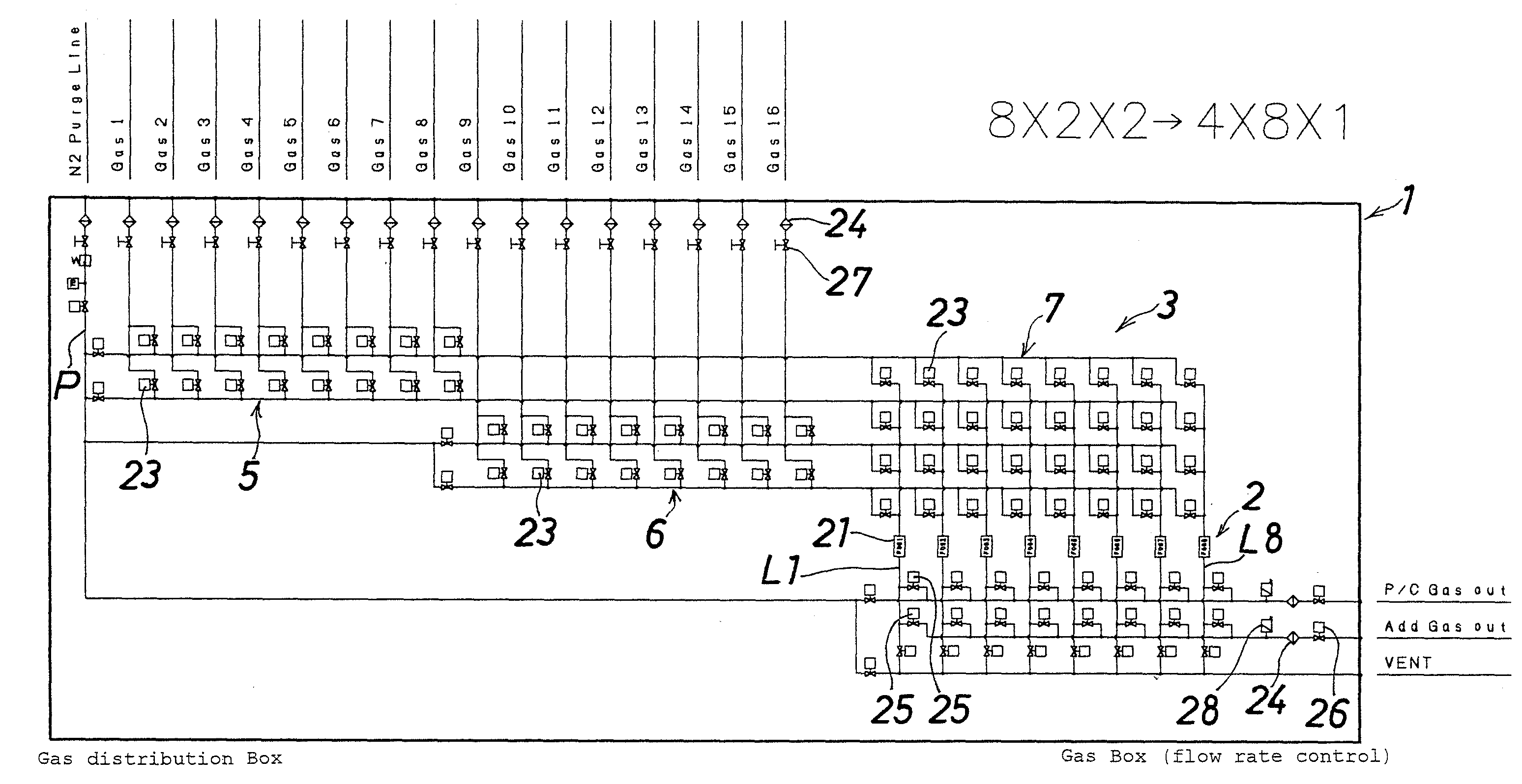
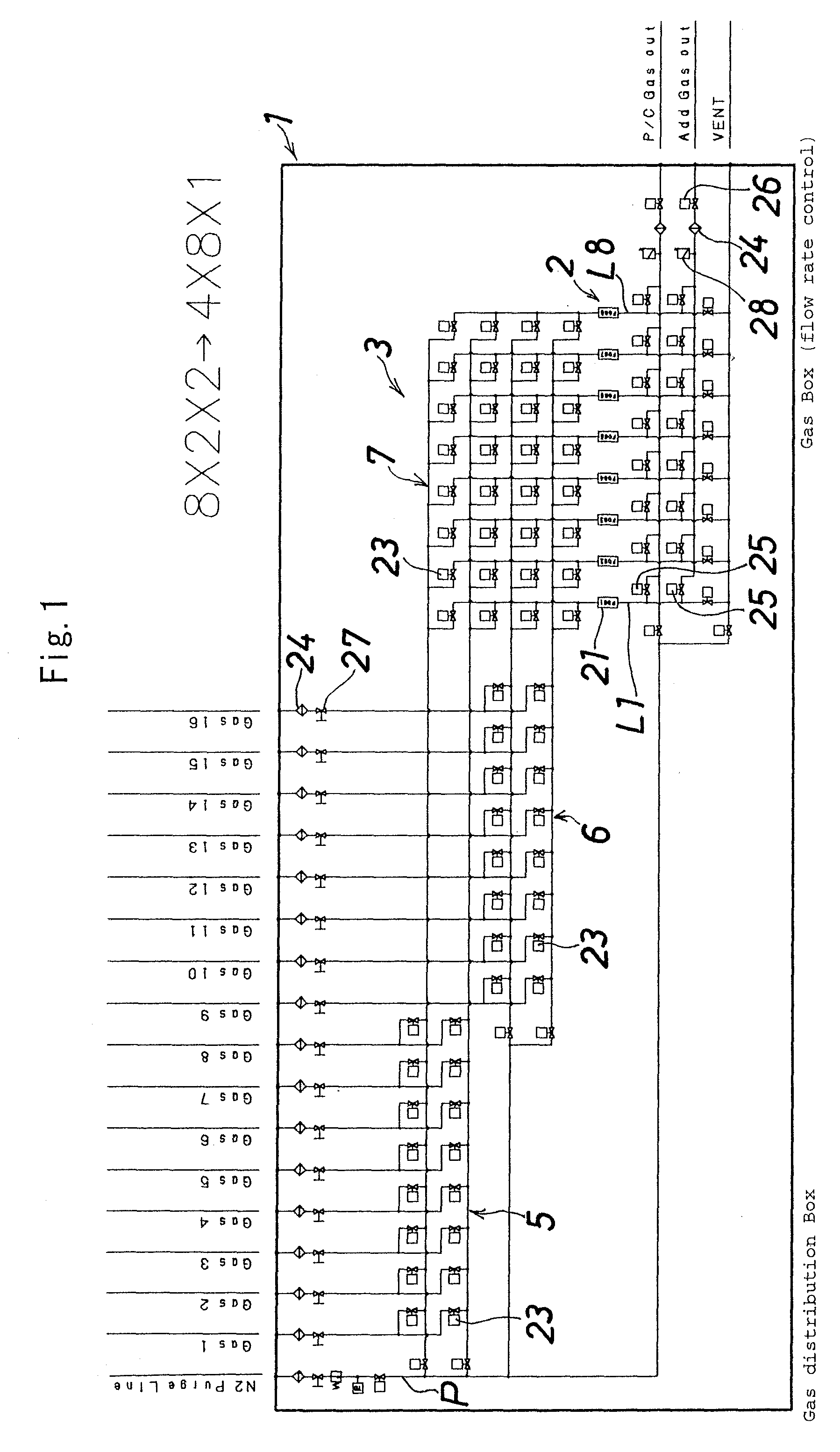
[0050]FIG. 1 shows the fluid control apparatus according to the present invention.
[0051]The fluid introducing unit (3) of the present embodiment is divided into three parts: a first and a second inlet-side shutoff / open parts (5) (6) disposed on the inlet side, each including 2×N / 2 on-off valves (23), and a fluid controlling unit-side shutoff / open part (7) disposed between the first and second inlet-side shutoff / open parts (5) (6) and a fluid controlling unit (2), including 4×M on-off valves (23).
[0052]The first and second inlet-side shutoff / open parts (5) (6) divide N inlets into two inlet-side shutoff / open parts, and each has N / 2 inlets and two outlets. As a result, the total number of outlets of the first and second inlet-side shutoff / open parts (5) (6) (number of inlets for the fluid controlling unit-side shutoff / open part (7)) is (2+2), and by forming the fluid controlling unit-side shutoff / open part (7) of 4×M on-off valves (23) in correspondence with the total of 4 outlets, M ...
second embodiment
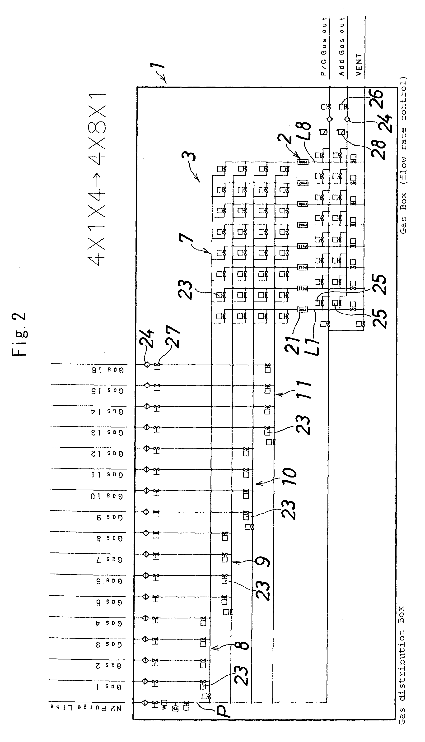
[0055]FIG. 2 shows the fluid control apparatus of the present invention.
[0056]A fluid introducing unit (3) of the present embodiment is divided into five parts: a first to a fourth inlet-side shutoff / open parts (8) (9) (10) (11) disposed on the inlet side, each including N / 4 on-off valves (23), and a fluid controlling unit-side shutoff / open part (7) including 4×M on-off valves (23), disposed between the first to fourth inlet-side shutoff / open parts (8) (9) (10) (11) and a fluid controlling unit (2).
[0057]The fluid controlling unit-side shutoff / open part (7) has the same constitution as that of the first embodiment. A difference from the first embodiment lies in that the first and second inlet-side shutoff / open parts (5) (6) in the first embodiment are further divided, and the four inlet-side shutoff / open parts (8) (9) (10) (11) are formed. According to the constitution of the second embodiment, since each one kind of fluid is introduced into each of the first to fourth inlet-side sh...
third embodiment
[0059]FIG. 3 shows the fluid control apparatus of the present invention.
[0060]A fluid introducing unit (3) of the present embodiment is divided into 6 parts: a first to a fourth inlet-side shutoff / open parts (8) (9) (10) (11) disposed on the inlet side, each including N / 4 on-off valves (23), and a first and a second fluid controlling unit-side shutoff / open parts (12) (13) each including 2×M / 2 on-off valves (23), disposed between the first to fourth inlet-side shutoff / open parts (8) (9) (10) (11) and a fluid controlling unit (2).
[0061]The first to fourth inlet-side shutoff / open parts (8) (9) (10) (11) have the same constitution as that of the second embodiment. A difference between the third embodiment and the second embodiment lies in that the fluid controlling unit-side shutoff / open part (7) in the second embodiment is divided into two fluid controlling unit-side shutoff / open parts (12) (13). The first and second fluid controlling unit-side shutoff / open parts (12) (13) as a whole h...
PUM
| Property | Measurement | Unit |
|---|---|---|
| Fraction | aaaaa | aaaaa |
| Force | aaaaa | aaaaa |
| Molar density | aaaaa | aaaaa |
Abstract
Description
Claims
Application Information