Brush DC motor with reduction mechanism

a brush dc motor and reduction mechanism technology, applied in the field of brushes dc motors with reduction mechanisms, can solve the problems of reducing transmission efficiency, reducing transmission efficiency, and affecting the operation of the brush dc motor, and achieve the effect of easy maintenance and coupling structur

Active Publication Date: 2012-02-09
HIWIN MIKROSYST
View PDF2 Cites 39 Cited by
  • Summary
  • Abstract
  • Description
  • Claims
  • Application Information

AI Technical Summary

Benefits of technology

[0008]It is therefore a primary object of the present invention to provide a brush DC motor with reduction mechanism, in which the reduction mechanism is integrated and arranged in a space at one end of the brush DC motor. Accordingly, the coupling structure between the brush DC motor and the reduction mechanism is simplified and compacted, whereby the brush DC motor is lightweight and easy to maintain.

Problems solved by technology

Conventionally, a shaft coupler or other transmission components are needed to transmit the power of the output shaft to the transmission mechanism in a relatively complicated manner.
Accordingly, the power is transmitted via numerous transmission components, which abrade each other to cause a loss of part of energy.
Moreover, the numerous transmission components prolong the transmission path of the power and thus lower the transmission efficiency.
These omissible components lead to high manufacturing and maintenance cost and will working precision.
Moreover, these omissible components make it harder to fully utilize the space for the deployment.

Method used


Image

  • Brush DC motor with reduction mechanism
  • Brush DC motor with reduction mechanism
  • Brush DC motor with reduction mechanism

Examples


Embodiment Construction

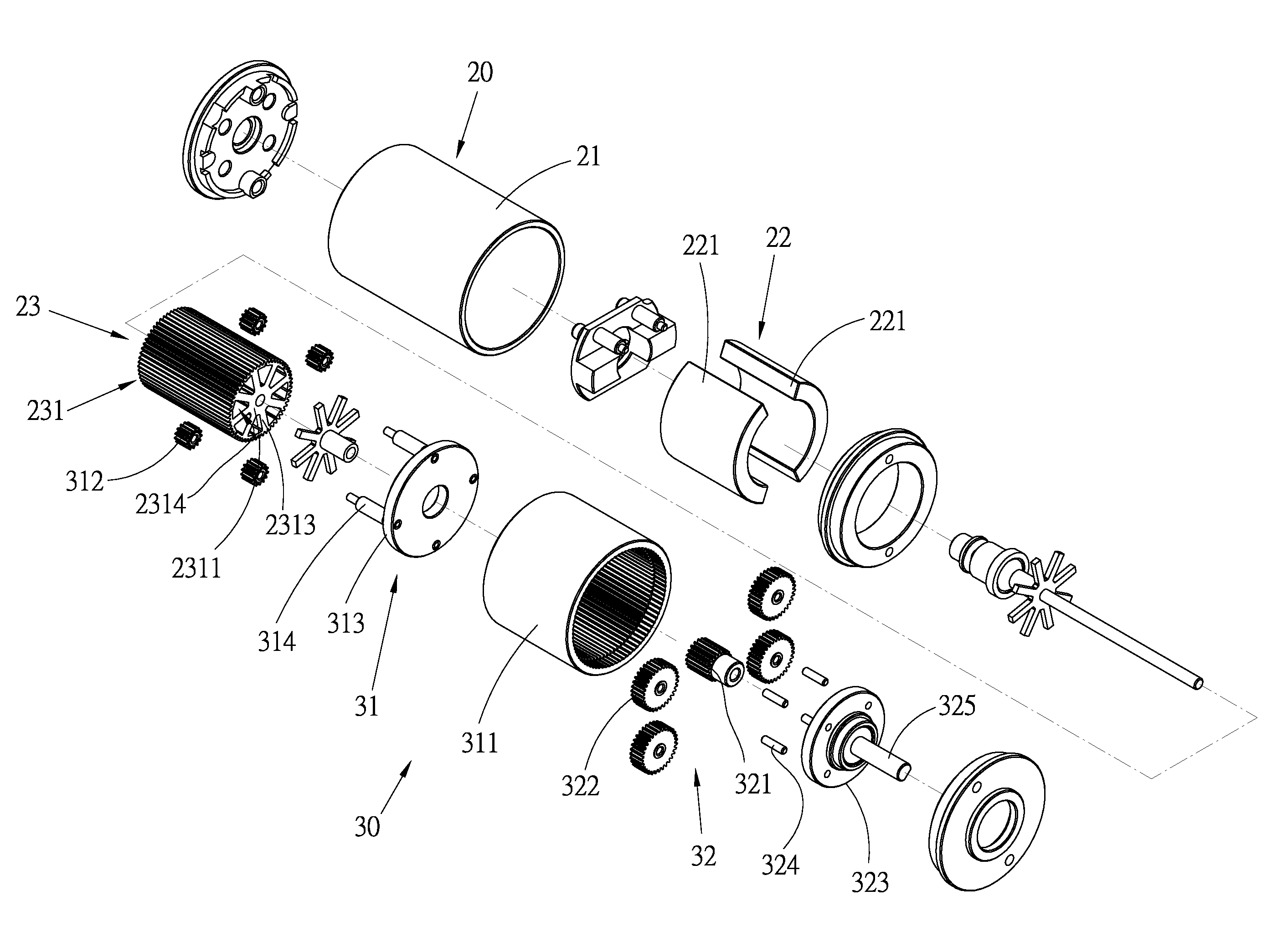
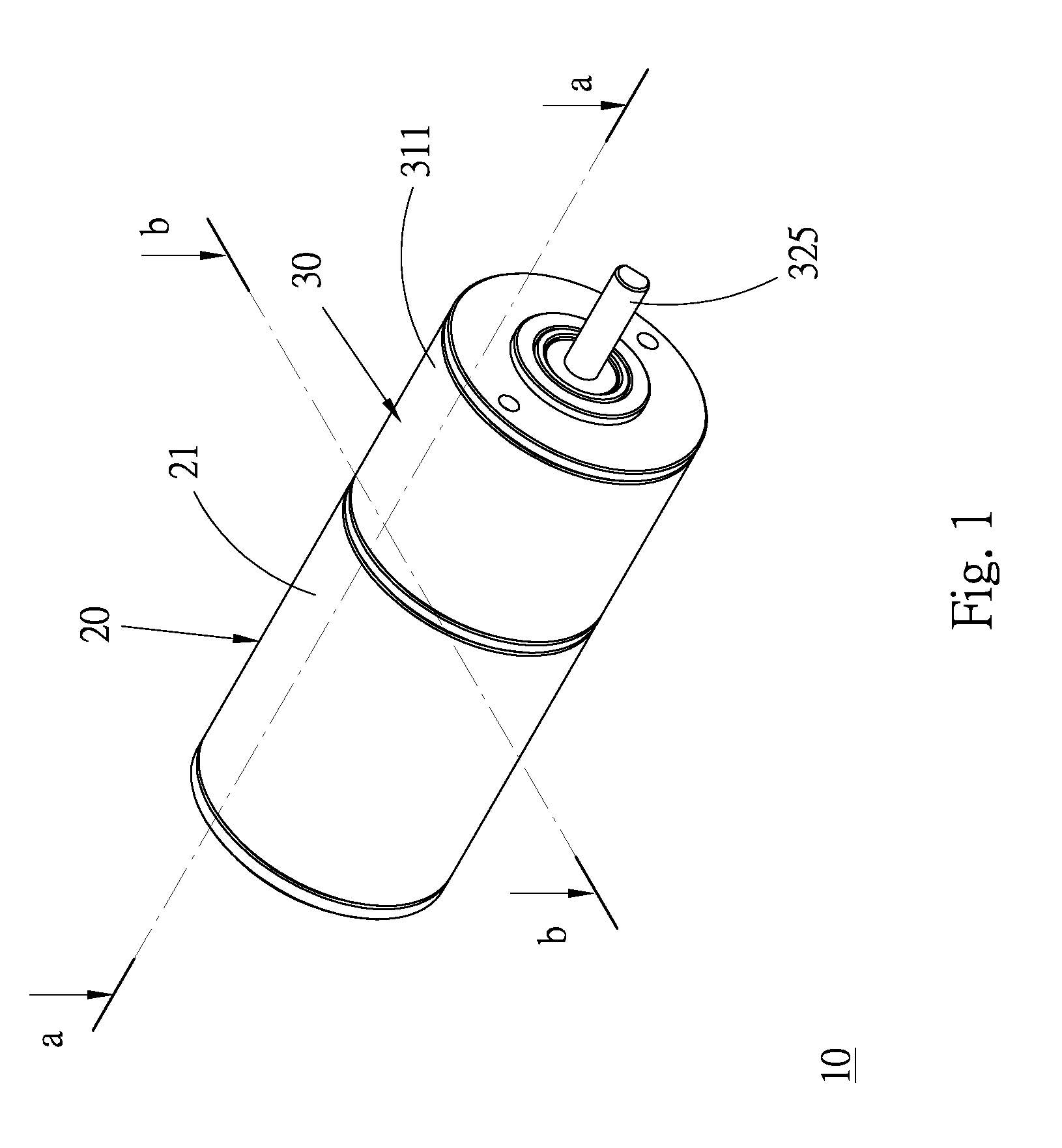
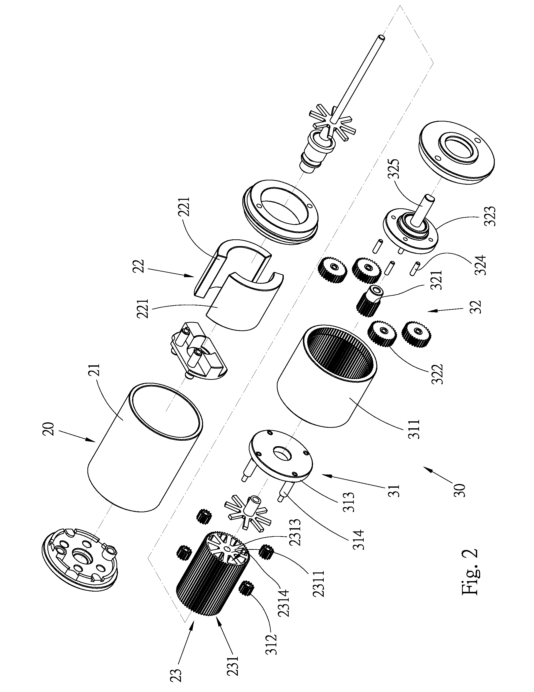
[0020]Please refer to FIGS. 1 to 6. According to a preferred embodiment, the brush DC motor 10 with reduction mechanism of the present invention mainly includes a brush DC motor 20 and a reduction mechanism 30.

[0021]The brush DC motor 20 is a conventional two-pole and eight-slot type permanent magnet brush DC motor. The brush DC motor 20 is composed of a motor case 21, a stator section 22 and a rotor section 23.

[0022]The motor case 21 is a tubular body with a certain inner diameter for receiving the stator section 22 and the rotor section 23 therein.

[0023]The stator section 22 includes two permanent magnets 221 in the form of arcuate pieces. The convex faces of the permanent magnets 221 are attached and affixed to inner circumference of the motor case 22. The curvature center of the permanent magnets 221 coincides with the axis of the motor case 21.

[0024]The rotor section 23 has a substantially cylindrical core 231 coaxially received in the motor case 21. One end of the core 231 ext...


PUM


Abstract

A brush DC motor with reduction mechanism includes: a brush DC motor including a motor case, a stator section and a rotor section having a substantially cylindrical core, the stator section and the rotor section being received in the motor case; and a first reducing section drivable by the motor. The first reducing section includes a first sun gear, an external ring gear positioned around the sun gear and several planetary gears held between the external ring gear and the sun gear and engaged with the sun gear and the external ring gear. The first reducing section further includes a planetary carrier for locating the planetary gears in their true positions. Multiple parallel linear splines are formed on a circumference of the core at intervals. One end of the core with the splines formed on the circumference of the end serves as the sun gear of the first reducing section.

Description

BACKGROUND OF THE INVENTION[0001]1. Field of the Invention[0002]The present invention relates generally to a motor, and more particularly to a brush DC motor with reduction mechanism.[0003]2. Description of the Related Art[0004]A conventional motor serves to convert electrical energy into mechanical energy. The motor can drive a load in a direct drive manner. Alternatively, in general, an independent transmission mechanism must be additionally arranged between the motor output shaft and the load. The torque output by the output shaft of the motor is adjusted and changed by the transmission mechanism and then transmitted to the load.[0005]Conventionally, a shaft coupler or other transmission components are needed to transmit the power of the output shaft to the transmission mechanism in a relatively complicated manner. Accordingly, the power is transmitted via numerous transmission components, which abrade each other to cause a loss of part of energy. Moreover, the numerous transmiss...

Claims


Application Information

Patent Timeline
Patent Type & Authority Applications(United States)
IPC IPC(8): H02K7/116
CPCH02K7/116
Inventor CHEN, GUAN-CHENCHIANG, HSIN-AN
Owner HIWIN MIKROSYST
Why Eureka
Try Eureka