Water-proof dust-proof and salty-mist-proof cooling fan

Inactive Publication Date: 2012-02-09
ROTECHNIC
View PDF9 Cites 19 Cited by
  • Summary
  • Abstract
  • Description
  • Claims
  • Application Information

AI Technical Summary

Benefits of technology

[0015]Summing up the above, the cooling fan of the present invention has the following advantages: the technology of placing the stators and the circuit board elements in tight-sealing enclosure replaces the vacuum film plating method and glue pouring method of the prior art, hereby providing effective protection for the stators and the circuit board elements, in achieving the purpose of water-proof, dust-proof, and salty-mist-proof of the cooling fan; the tightly fit cooperation of the snap-fit hooks and the snap-fit slots is utilized to achieve tight sealing and easy installation; the formation of a structure such that lead wires can be led to outside from the lateral tube in the sleeve, thus facilitating tight-sealing tests of the tight-sealing enclosure and ensuring quality of cooling fan; and moreover, a water sealing plug is provided on one end of the sleeve, to enhan

Problems solved by technology

Along with the ever expanding fields of cooling fan applications, from CPU, server, power supply, to the communication equipment, and outdoor machine stations, the environment the cooling fan is utilized is getting increasingly severe.
Usually, in a damp and salty mist environment, the stator and circuit board are under no protection, thus the silicon steel sheet of the stator tends to get rusty and be corroded, and the elements on the circuit board are liable to get short-circuited and burned out, such that the cooling fan can not function normally.
In a vacuum film plating method, the entire stators and circuit board elements are plated with a layer of film, so as to achieve water-proof effect, Yet, since this layer of film fits tightly on the surface of an object, and in the film plating process, the stress in this layer of film tends to damage elements on a circuit board, so th

Method used


Image

  • Water-proof dust-proof and salty-mist-proof cooling fan
  • Water-proof dust-proof and salty-mist-proof cooling fan
  • Water-proof dust-proof and salty-mist-proof cooling fan

Examples


Example

[0021]The purpose, construction, features, functions and advantages of the present invention can be appreciated and understood more thoroughly through the following detailed descriptions with reference to the attached drawings.

[0022]In the following, a detailed description of the present invention is given through real embodiments together with the attached drawings.

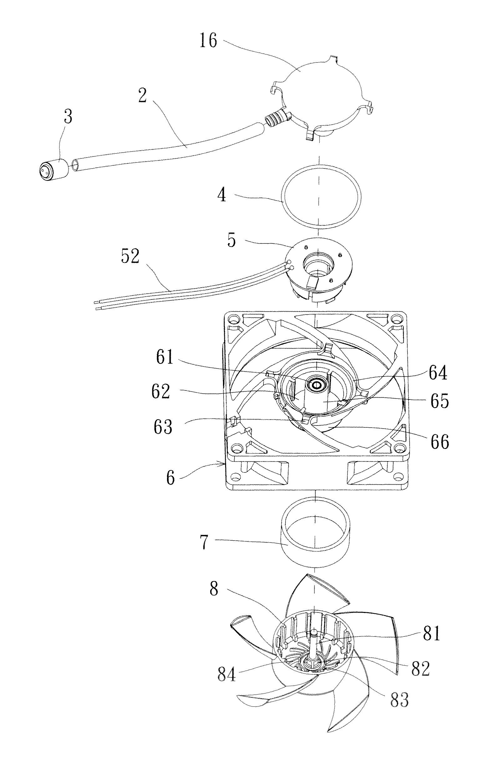
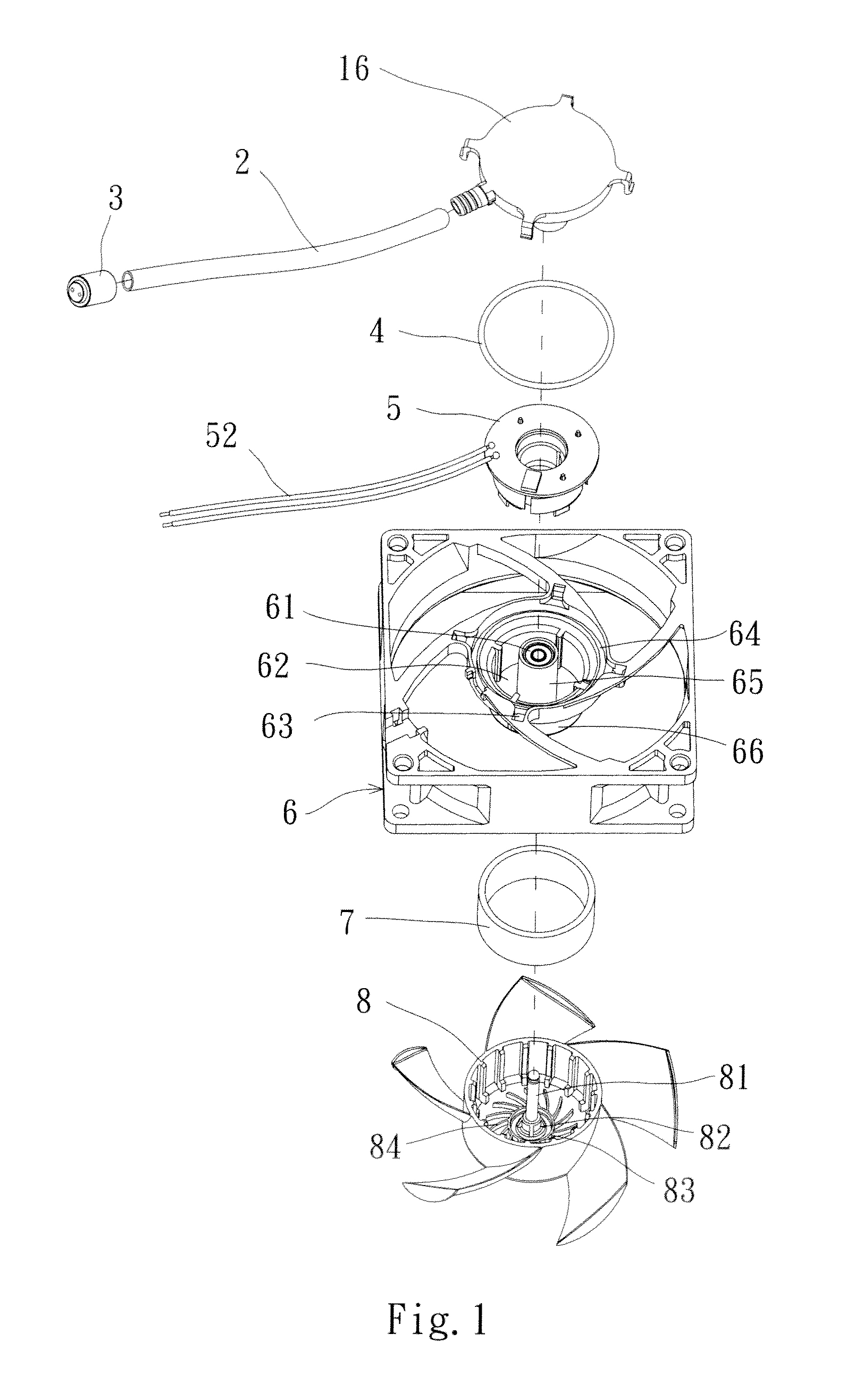
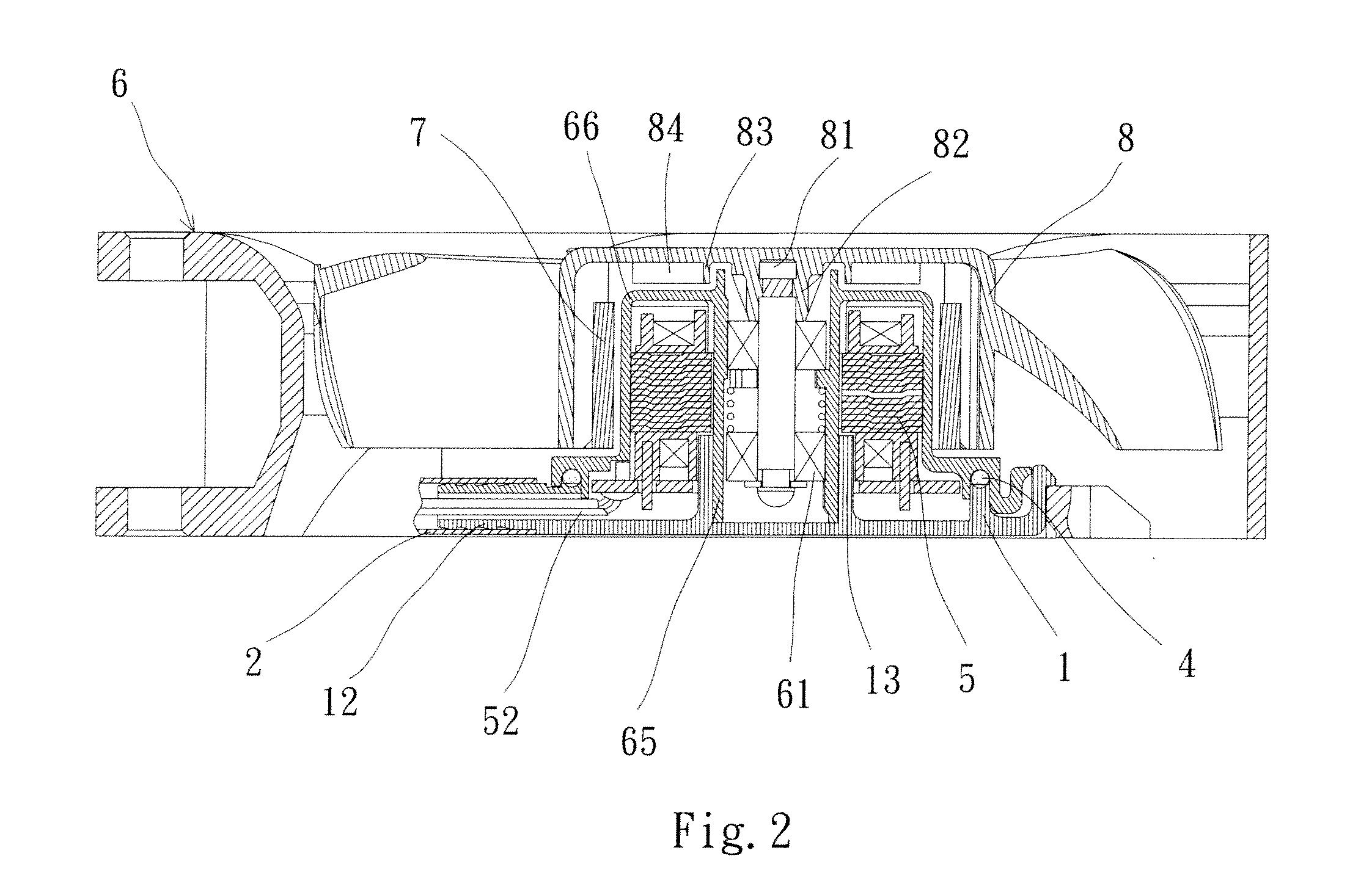
[0023]Firstly, refer to FIGS. 1-3 for an exploded view, cross section view, and top view of water-proof dust-proof and salty-mist-proof cooling fan according to the present invention respectively. As shown in FIGS. 1-3, the water-proof dust-proof and salty-mist proof cooling fan of the present invention comprises: a fan frame 6, which is provided with a fixing round stage 66 inside, and a fixing sleeve 65 is disposed at the center of the fixing round stage 66, inside the fixing sleeve 65 is provided with bearings 61; a blind hole 62, provided between the fixing round stage 66 and a fixing sleeve 65, and stators and circu...


PUM


Abstract

A water-proof dust-proof and salty-mist proof cooling fan, comprising: a fan frame, which is provided with a fixing round stage inside, and a fixing sleeve is disposed in a center of said fixing round stage; a ring-shaped U slot is provided in a bottom end surface of said round stage, such that a sealing circle is provided in said ring-shaped U slot; a water-proof cover body, fixedly connected to said fan frame through said sealing circle; and a fan-blade hub, where an inverse cone-shaped fixing table is provided protruding from a cavity center of said fan-blade hub, and said fixing table is connected to a main axis. Said round stage is a blind hole, with its open end provided at a bottom portion of said fan frame, such that said round stage, said sealing circle, and said cover body together form a tight-sealing enclosure.

Description

BACKGROUND OF THE INVENTION[0001]1. Field of the Invention[0002]The present invention relates to a cooling fan, and in particular to a water-proof dust-proof and salty-mist-proof cooling fan.[0003]2. The Prior Arts[0004]A cooling fan is mainly composed of rotors, stators, rolling bodies, and circuit boards. Along with the ever expanding fields of cooling fan applications, from CPU, server, power supply, to the communication equipment, and outdoor machine stations, the environment the cooling fan is utilized is getting increasingly severe. Usually, in a damp and salty mist environment, the stator and circuit board are under no protection, thus the silicon steel sheet of the stator tends to get rusty and be corroded, and the elements on the circuit board are liable to get short-circuited and burned out, such that the cooling fan can not function normally.[0005]Presently, a cooling fan is made by two kinds of methods: a vacuum film platting method, and glue pouring method.[0006]In a va...

Claims


Application Information

Patent Timeline
IPC IPC(8): H02K5/10
CPCF04D25/0613F04D29/083H02K7/14H02K5/10F04D29/646
Inventor LIU, CHING-TANGLU, TAI-YINGYI, TUNG-SHENG
Owner ROTECHNIC
Why Eureka
Try Eureka