Rotating body for fluid dynamic bearing capable of being thinned and being improved in rotational accuracy and method of producing the rotating body for fluid dynamic bearing

a technology of fluid dynamic bearing and rotating body, which is applied in the direction of magnetic recording, data recording, instruments, etc., can solve the problems of reducing the stiffness of the hub, affecting the rotational accuracy of the rotating body, and deteriorating the stability of the supporting shaft, etc., and achieves the effect of easy bending, easy bending, and easy bending

Inactive Publication Date: 2012-02-09
SAMSUNG ELECTRO MECHANICS JAPAN ADVANCED TECHNOLOGY CO LTD
View PDF4 Cites 7 Cited by
  • Summary
  • Abstract
  • Description
  • Claims
  • Application Information

AI Technical Summary

Benefits of technology

[0011]According to the embodiment, because the cylindrical portion, the protruding portion, the annular portion, and the mounting seat portion are formed integrally with each other by a press process, the connection strength of the connection part between the cylindrical portion and the protruding portion and the squareness of the joint between them can be easily secured. Further, the dimensional accuracy of the whole of the cylindrical portion, the protruding portion, the annular portion, and the mounting seat portion can be easily secured by performing the adjustment of the processed dimensions of the four portions with a grinding process and a polishing process, etc., after any one of the four portions has been determined as a supporting reference. Furthermore, by subjecting the cylindrical portion, the protruding portion, the annular portion, and the mounting seat portion to surface coating, such as, for example, electroless nickel plating, gas generation from the material can be prevented, and protection of the surface and improvement in the surface hardness can also be achieved.

Problems solved by technology

If the length of a shaft to be housed in a sleeve of which part of a fixed body is composed is made small for the thinning, the stability of supporting the shaft is deteriorated, and hence there arises the fear that eccentricity during rotation may be caused.
Alternatively, thinning of the hub can be considered for the thinning of the whole rotating device; however, the thinning thereof induces a decrease in the stiffness as a hub as well as shortening of the axial connection margin occurring when the hub is connected to the shaft.
The shortening of the connection margin induces a decrease in the connection strength between the shaft and the hub and a decrease in the squareness occurring when the two parts are connected together, and hence there arises the problem that stable high-speed rotation cannot be obtained as a rotating device for a fluid dynamic nearing.
Alternatively, it can be considered that only the part of the hub corresponding to a connection margin is to be extended in the axial direction of the shaft; however, the length of the shaft to be housed in the sleeve is shortened by the length equal to the extended connection margin, and hence the same problems arise as in the aforementioned shortening of the shaft.

Method used


Image

  • Rotating body for fluid dynamic bearing capable of being thinned and being improved in rotational accuracy and method of producing the rotating body for fluid dynamic bearing
  • Rotating body for fluid dynamic bearing capable of being thinned and being improved in rotational accuracy and method of producing the rotating body for fluid dynamic bearing
  • Rotating body for fluid dynamic bearing capable of being thinned and being improved in rotational accuracy and method of producing the rotating body for fluid dynamic bearing

Examples


Embodiment Construction

[0024]The invention will now be described by reference to the preferred embodiments. This does not intend to limit the scope of the present invention, but to exemplify the invention.

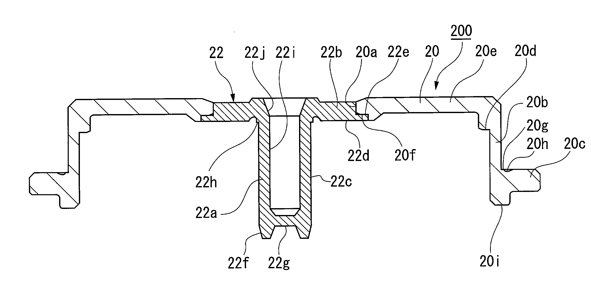
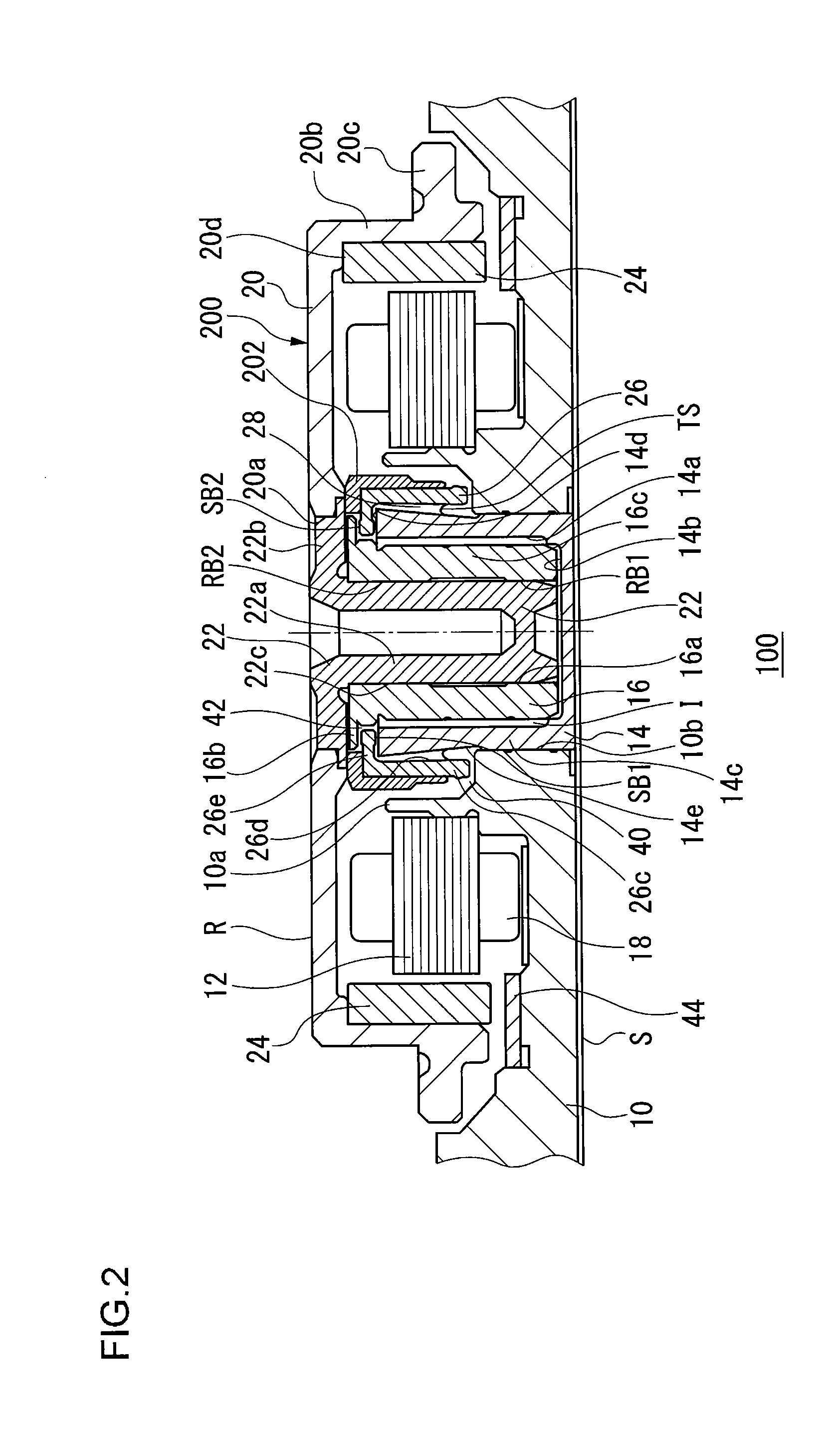
[0025]Hereinafter, the preferred embodiments of the present invention will be described with reference to the accompanying drawings. The same or equivalent constituting elements and members illustrated in each drawing shall be denoted by the same reference numerals, and duplicative explanations will be omitted. Dimensions of members illustrated in each drawing are appropriately enlarged or reduced for easy understanding. Part of the members not important for describing the embodiments are omitted from each drawing.

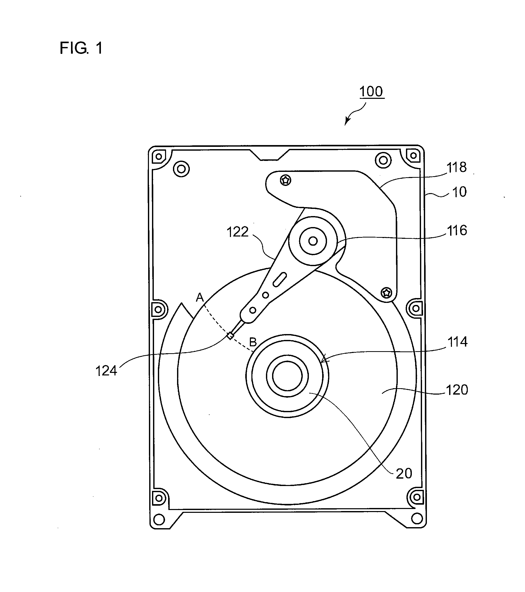
[0026]FIG. 1 is an illustrative view for explaining the internal structure of a disk drive device 100, which is one example of a rotating device to which a rotating body for a fluid dynamic bearing according to the present embodiment has been applied. FIG. 1 illustrates a state in which a cover...


PUM

PropertyMeasurementUnit
axial lengthaaaaaaaaaa
outer circumferenceaaaaaaaaaa

Abstract

A rotating body for a fluid dynamic bearing used for rotating a recording disk that has been mounted therein include: a rotating shaft portion in which a cylindrical portion that serves as a rotating shaft and a protruding portion extended radially outward from one end of the cylindrical portion are formed integrally with each other; and a hub that is to be connected to the end portion near to the outer circumference of the protruding portion and that has a mounting seat portion on which the recording disk is to be mounted.

Description

CROSS-REFERENCES TO RELATED APPLICATIONS[0001]This application is based upon and claims the benefit of priority from the prior Japanese Patent Application No. 2010-174742 filed Aug. 3, 2010 entire content of which is incorporated herein by reference.BACKGROUND[0002]1. Field of the Invention[0003]The present invention relates to a rotating body for a fluid dynamic bearing and a method of producing the rotating body for a fluid dynamic bearing, and in particular, to a technique in which the rotational accuracy of a rotating body can be secured while the rotating body is thinned.[0004]2. Description of the Related Art[0005]Electronic apparatuses recently deal with a huge amount of data, and accordingly rotating devices, such as hard disk drives (HDDs), are widely mounted therein as recording apparatuses. In a rotating device mounted in such an electronic apparatus, read / write of a huge amount of data is achieved by stably rotating a recording disk at high-speed. In order to make it pos...

Claims


Application Information

Patent Timeline
Patent Type & Authority Applications(United States)
IPC IPC(8): G11B17/028G11B5/127
CPCY10T29/49021G11B19/2009
Inventor MURAMATSU, AKIRAYAMADA, TAKUJI
Owner SAMSUNG ELECTRO MECHANICS JAPAN ADVANCED TECHNOLOGY CO LTD
Why Eureka
Try Eureka