
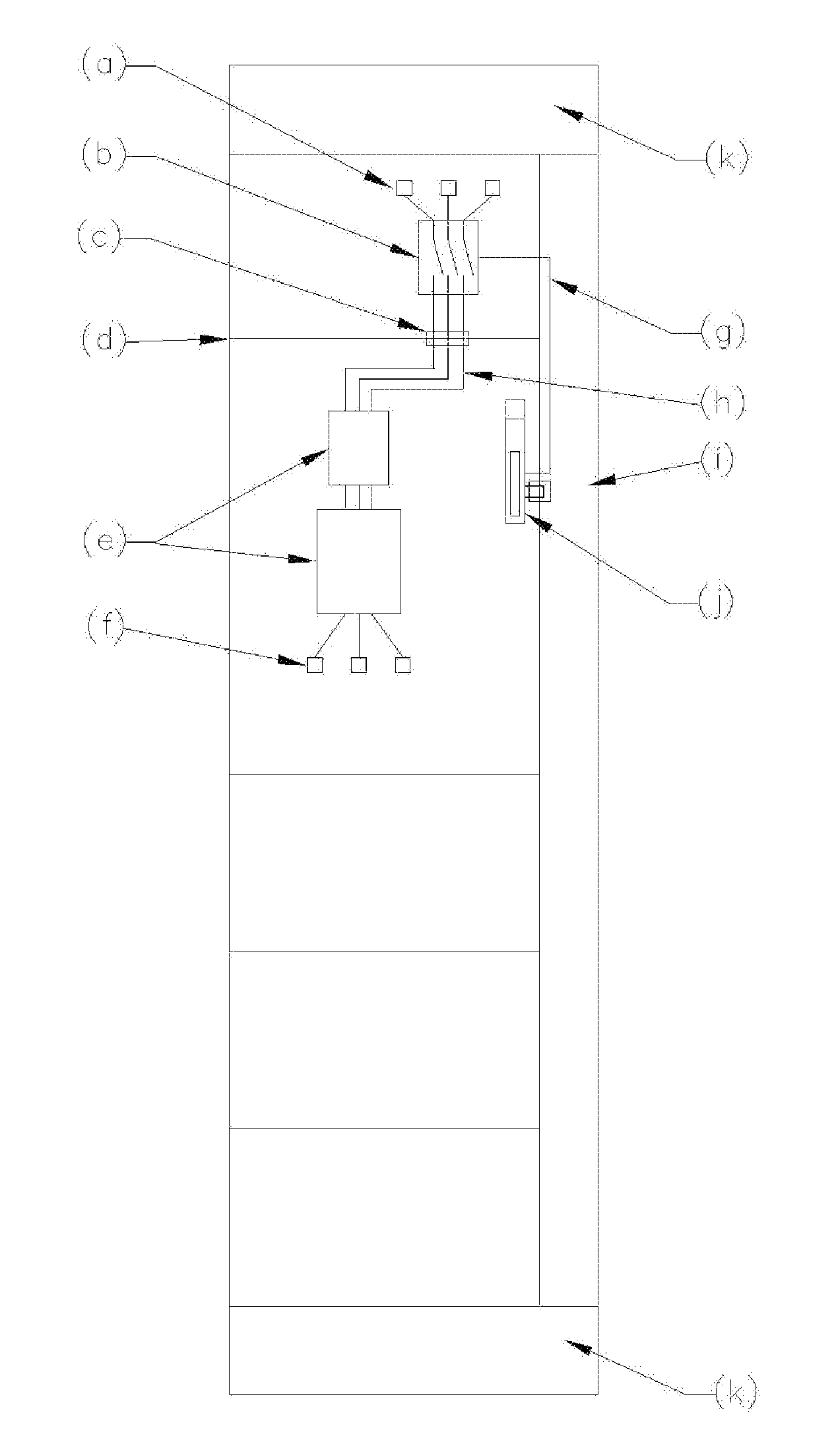
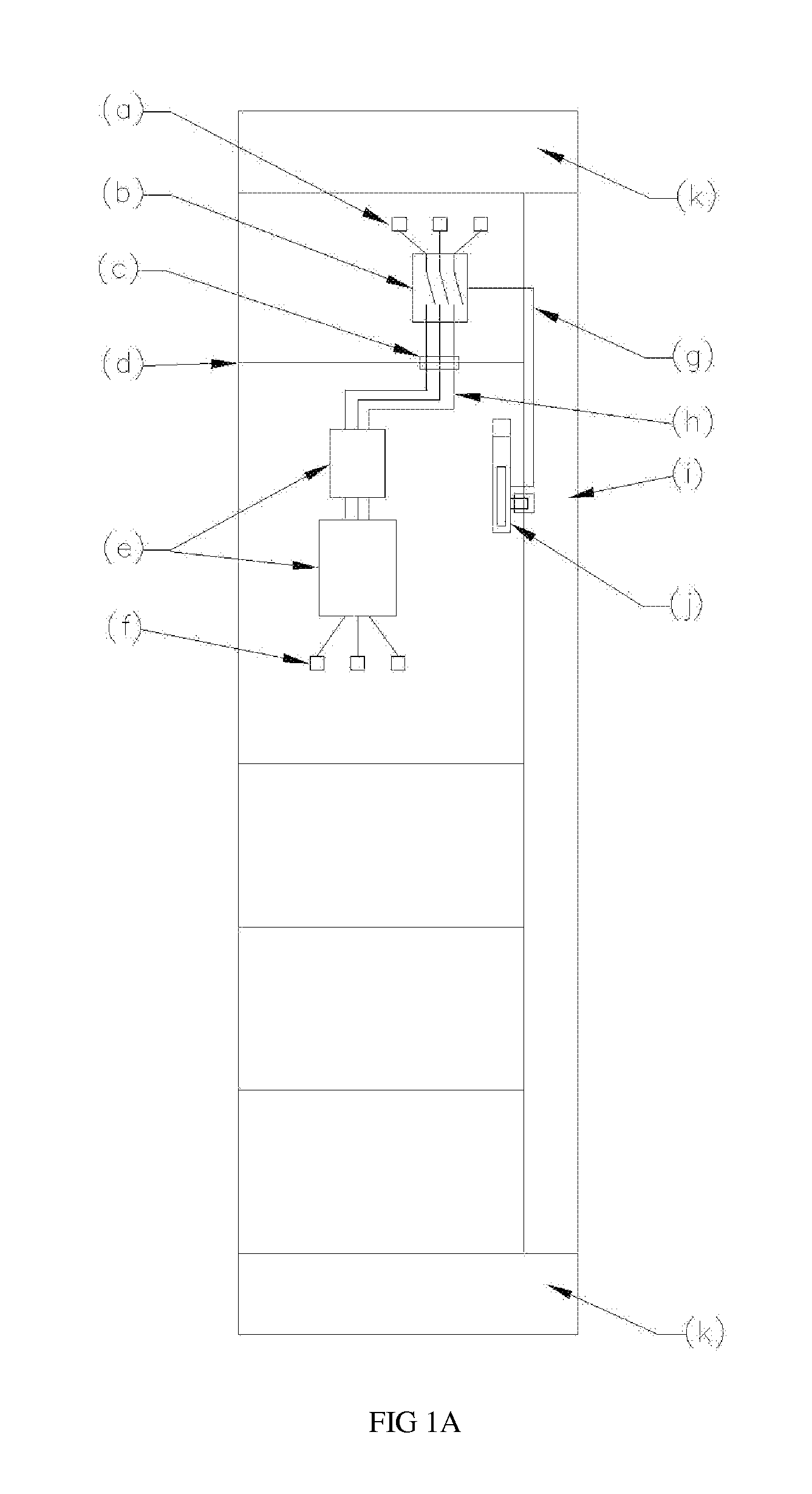
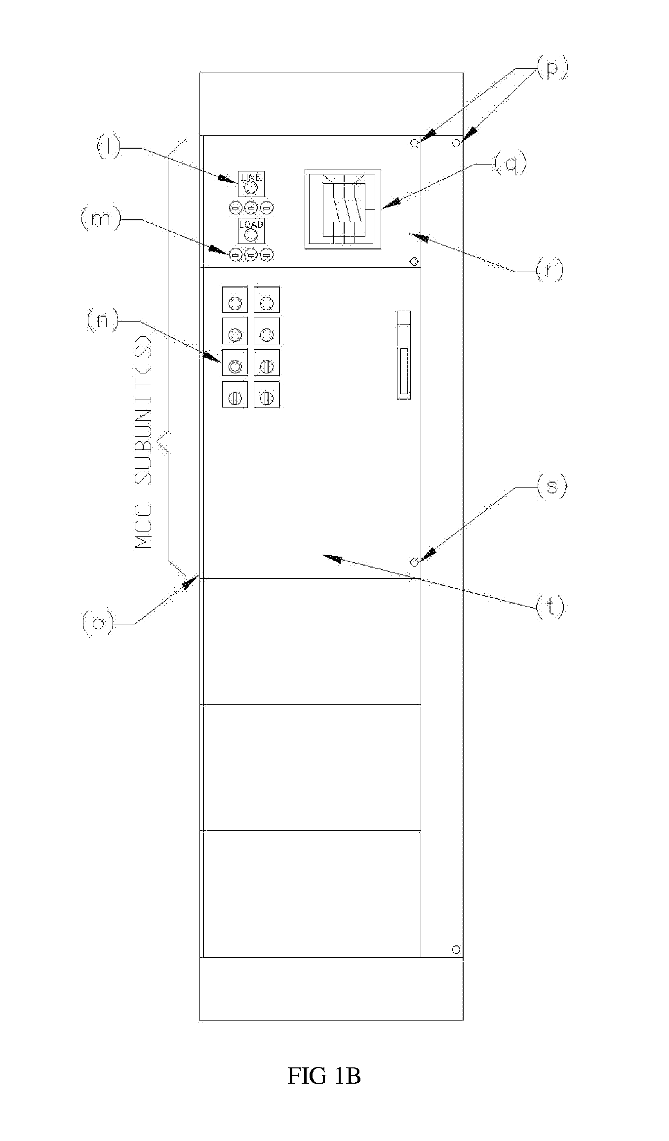
Motor Control Center Subunit(s) (bucket(s)) with compartmentalized disconnect associated with a distinctly separate load section.

Inactive Publication Date: 2012-02-09
GRINDELAND BRUCE WILLIAM
View PDF0 Cites 0 Cited by
  • Summary
  • Abstract
  • Description
  • Claims
  • Application Information

AI Technical Summary

Benefits of technology

[0008]My invention isolates, through compartmentalization, energized components apart from de-energized components, decreasing the hazards and cumbersome nature as it applies to the components included. My invention includes an operator that grants access to the compartment which can be completely de-energized and does NOT grant access to the compartment which still houses energized parts (to gain access to this compartment you would have to use special tools). My invention would also achieve a reduction in how often the disconnecting means, itself, would be disconnected from the MCC Bus by allowing the load compartment to be removed independently of the disconnect (when built as two separate subunits).

Problems solved by technology

This causes risks of arc flash and otherwise dangerous conditions to a person that is exposed to a Subunit / compartment that follows this conventional means of assembly.
Proper safety methods and procedures are cumbersome, leading to the potential for a person to not engage in the methods and / or procedures that are legally required to work within such a compartment and exposing themselves to unnecessary risks.

Method used


Image

  • Motor Control Center Subunit(s) (bucket(s)) with compartmentalized disconnect associated with a distinctly separate load section.
  • Motor Control Center Subunit(s) (bucket(s)) with compartmentalized disconnect associated with a distinctly separate load section.
  • Motor Control Center Subunit(s) (bucket(s)) with compartmentalized disconnect associated with a distinctly separate load section.

Examples


Embodiment Construction

[0013]The following description makes reference to line voltage. It is appreciated that such a term may refer to a variety of both common voltage ranges and unique voltages depending on context. However, it is appreciated that the present invention is intended for use in typical low-voltage (<600V) electrical systems and the purpose of the invention is to simplify compliance with safety regulations and procedures during maintenance. A typical example would consist of a system wherein supply voltage is 480 volts 3-phase. My invention describes an improvement to commonly used low-voltage motor control centers. Motor control centers are in common use in the electrical field and often referred to as MCC's.

[0014]Referring to the Drawings, a typical arrangement of the components in a preferred embodiment of the invention is shown. The overall enclosure, or MCC unit, contains within it a disconnecting device and load device(s) as commonly used in applications of electrical systems but isol...


PUM


Abstract

A Motor Control Center Subunit(s) (bucket(s)) with compartmentalized disconnect associated with a distinctly separate load compartment, consisting of multiple compartments arranged so as to allow service of the load compartment without exposure to line voltages. The invention removes the energized components from the associated loads they are feeding, thereby greatly reducing the health risks and decreasing the cumbersome nature of legally necessary methods and procedures that a person working within such a compartment would currently have to ascribe to. A key feature / distinction of this invention is that the disconnecting devices is remote mounted from the load controlling components, so that when the handle operator is switched to the OFF position there are no components (e.g. disconnecting device and / or its conductors) within the load compartment that remain energized by line voltage.

Description

CROSS-REFERENCE TO RELATED APPLICATIONS[0001]This system / assembly I have described can be used in the way I described a previous provisional patent(s) which I, Bruce William Grindeland, have filed (Application No: 61 / 370,896, Filing or 371(c) Date Aug. 5, 2010). This system / assembly also utilizes some concepts similar to those of (a) non-provisional patent(s) application(s) I have filed (Application No: 61 / 367,923 EFS ID: U.S. Pat. No. 8,095,378, application Ser. No: 13 / 190,337 EFS ID: U.S. Pat. No. 10,593,378, application Ser. No: 13 / 190,409 EFS ID: U.S. Pat. No. 10,593,981).STATEMENT REGARDING FEDERALLY SPONSORED RESEARCH OR DEVELOPMENT[0002]Not ApplicableREFERENCE TO SEQUENCE LISTING, A TABLE, OR A COMPUTER PROGRAM LISTING COMPACT DISC APPENDIX[0003]Not ApplicableBACKGROUND OF THE INVENTION[0004]The present invention relates to a Motor Control Center Subunit(s) (bucket(s)) with compartmentalized disconnect associated with a distinctly separate load section.[0005]Herein, where com...

Claims


Application Information

Patent Timeline
IPC IPC(8): H05K7/00
CPCH05K7/1432H05K7/14325
Inventor GRINDELAND, BRUCE WILLIAM
Owner GRINDELAND BRUCE WILLIAM
Learn More