Energy efficient transmission in a network

a network and energy-efficient technology, applied in data switching networks, power management, high-level techniques, etc., can solve the problems of not being able to properly synchronize the whole network, affecting the efficiency of network transmission, so as to achieve less energy-consumption

Active Publication Date: 2012-02-09
KONINKLIJKE PHILIPS ELECTRONICS NV
View PDF14 Cites 29 Cited by
  • Summary
  • Abstract
  • Description
  • Claims
  • Application Information

AI Technical Summary

Benefits of technology

[0006]An objective of the invention is thus to provide a method for transmitting packet in wireless networks that induces less energy-consumption than existing protocols.

Problems solved by technology

Thus, even if it is very efficient, it is not well adapted for BCC body-area networks whose topology is highly dynamic, since the nodes are worn by a user, and thus are susceptible to be added or removed at any time, thus impeding almost all attempts to properly synchronize the whole network.
Moreover, since devices in this type of network might be worn all day long for only a few transmission period, synchronization is not really useful, and represents a waste of energy.
However the long preamble is a significant overhead.
Indeed, as soon as a receiving node catches a long preamble indicating that a transmission will start; it has to wait until the end of the preamble before getting the data, which represents a considerable loss of energy.
However, these protocols are not as energy-efficient as it would be expected for body-area networks such as medical sensor networks comprising sensor devices laid on a user's body.

Method used


Image

  • Energy efficient transmission in a network
  • Energy efficient transmission in a network
  • Energy efficient transmission in a network

Examples


Embodiment Construction

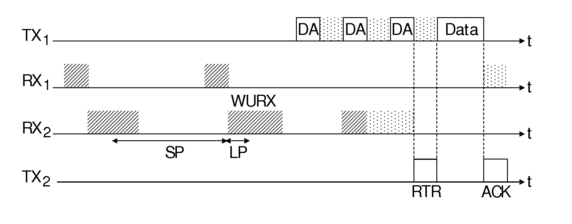
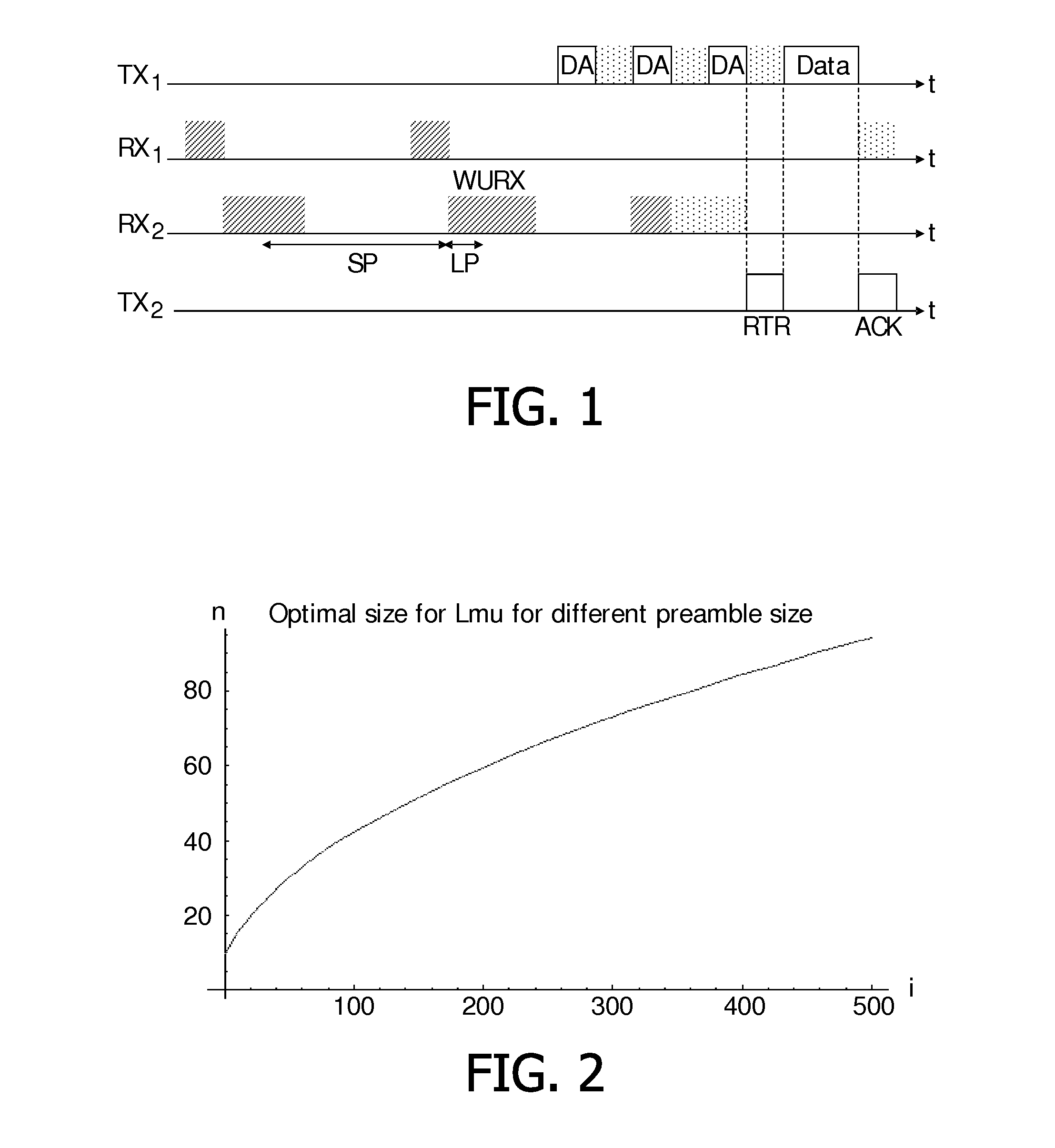
[0042]The present invention relates to a method for data packet transmission in a network comprising several communication devices, called nodes in this description. In a particular embodiment, these nodes are part of a body-area network using body-coupled communication, thus the nodes may be worn on a user's body. A BCC network often comprises nodes that are either worn by the user on his body or touched by the user, generally for a short time. The number of nodes that are part of the network may therefore be small, for example around ten. Moreover, the topology of such a network, i.e. the number of nodes in the network and their emplacement, is highly dynamic. Indeed, if a user wears an identifier in order to be identified at a door, the network is composed of a single node most of the day and of two nodes for very short period of time. Another example could be a user wearing many BCC-enabled multimedia devices which continuously guard themselves against theft. In that case the us...


PUM


Abstract

The present invention relates to a method for data packet transmissions between a source node and a destination node in a network, the method comprising: —the nodes being configured with an initial sleeping time period duration SPinit and an initial wake-up time period duration LPinit, —the source node sending a preamble, segmented in micro-preambles, for indicating the beginning of a transmission, the micro-preambles being separated by listening slots, —the destination node sending, upon receipt of at least one of the micro-preamble, a packet indicating its presence, called “Ready-To-Receive”, or RTR, packet, and—the source node sending, in response to the RTR packet, a data packet intended for the destination node, wherein the step of sending a preamble comprises: —the source node determining, based on SPinit and on LPinit, an optimal size of the micro-preambles that minimizes the overall energy consumption in the network for sending and receiving packets related to this preamble transmission.

Description

FIELD OF THE INVENTION[0001]The present invention relates to transmission of data in networks, namely in body area networks.[0002]This invention is, for example, relevant for networks carrying out body-coupled communication (BCC), which consists in sending information over the human body via electric field. More precisely, the invention relates to low-power transmissions methods for this type of network.BACKGROUND OF THE INVENTION[0003]Many medium access control protocols for wireless sensor networks have been proposed for allowing low power transmissions in these networks whose nodes are generally energy-restricted, due to the fact that they are often battery powered. Actually, in these networks, nodes periodically go to sleep and wake-up using the same schedule. Then, when a node wants to transmit a packet, it knows when all the network will be awaken and can transmit at this time. Such a method requires perfect synchronization of the network. Thus, even if it is very efficient, i...

Claims


Application Information

Patent Timeline
Patent Type & Authority Applications(United States)
IPC IPC(8): H04L12/28
CPCH04L12/12H04L12/40039Y02D30/50H04W52/02
Inventor CORROY, STEVEN
Owner KONINKLIJKE PHILIPS ELECTRONICS NV
Why Eureka
Try Eureka