Active/standby operation of a femtocell base station

a technology of active/standby operation and femtocell base station, which is applied in the field of wireless communications, can solve the problems of increasing radio interference and radio emissions in nearby areas, energy waste, and unsuitable approaches for femtocell base stations, and achieves the effect of reducing the operation and facilitating communication

Active Publication Date: 2012-02-09
SEMTECH CORP
View PDF4 Cites 35 Cited by
  • Summary
  • Abstract
  • Description
  • Claims
  • Application Information

AI Technical Summary

Benefits of technology

[0011]According to another aspect of the present invention there is provided a computer program product comprising a memory having computer readable code embodied therein, for execution by a CPU, for performing a method for operating a femtocell base station, the method comprising: obtaining a list of one or more designated wireless devices capable of wireless communication with the femtocell base station; determining an operating condition of the femtocell base station, the operating condition indicative of a count of the designated wireless devices which are in a condition for wireless communication with the femtocell base station; and switching the femtocell base station between an active state and a standby state based on the operating condition, wherein the femtocell base station facilitates communication between one or more wireless devices and a communication network when in the active state, and wherein the standby state corresponds to reduced operation of the femtocell base station compared with the active state.

Problems solved by technology

For example, an owner of a femtocell base station may want to restrict access to their femtocell since they pay the expense of maintenance and the broadband connection to their premises.
The traditional practice of having radio equipment continually turned on can result in energy being wasted.
In addition to wasting energy, always-on radio equipment can increase radio interference and radio emissions in nearby areas.
However, these approaches are unsuitable for femtocell base stations, for example since they may require knowledge of the network traffic load and full ownership of the base stations by the MNO.
Furthermore, such solutions may not fully leverage the potential capabilities of a femtocell, for example as enabled by the availability of closed subscriber groups.

Method used


Image

  • Active/standby operation of a femtocell base station
  • Active/standby operation of a femtocell base station
  • Active/standby operation of a femtocell base station

Examples


example 1

[0083]FIG. 4 illustrates operations related to switching of a femtocell between a standby state 410 and an active state 440, in accordance with embodiments of the present invention. In this example, switching between states is performed using the scanning method in conjunction with a paging method and a data base query in accordance with a member self-updating method or network assisted method. In the standby state, the wireless interface may default to an OFF state 415 for predetermined periods of time. The OFF state 415 results in power savings at the femtocell and a reduction in potential interference due to radio activity. Wireless devices do not wirelessly communicate with the femtocell when the wireless interface is in the off state 415, however, in some embodiments, messages may still be received by the femtocell via its network interface, which may remain on substantially continuously or at least for predetermined periods during standby. The wireless interface transitions to...

example 2

[0090]FIG. 5 illustrates a database 510 configured to track current locations 518 of designated wireless devices514 in accordance embodiments of with the present invention. The database may be queried by the femtocell in determining an operating condition of the femtocell and / or a count of designated wireless devices which are in a condition for wireless communication with the femtocell base station.

[0091]The database 510 may be maintained in accordance with the member self-updating method or another method, such as the network assisted method, as described herein. The database may be stored in memory of the femtocell or another device, such as an auxiliary device or server operatively coupled to the femtocell via the network interface.

[0092]As illustrated in FIG. 5, a designated wireless device 550 may be configured to monitor 552 for changes in its location. When a change 554 is detected, for example corresponding to handover between macrocells or femtocells, substantial change in...

example 3

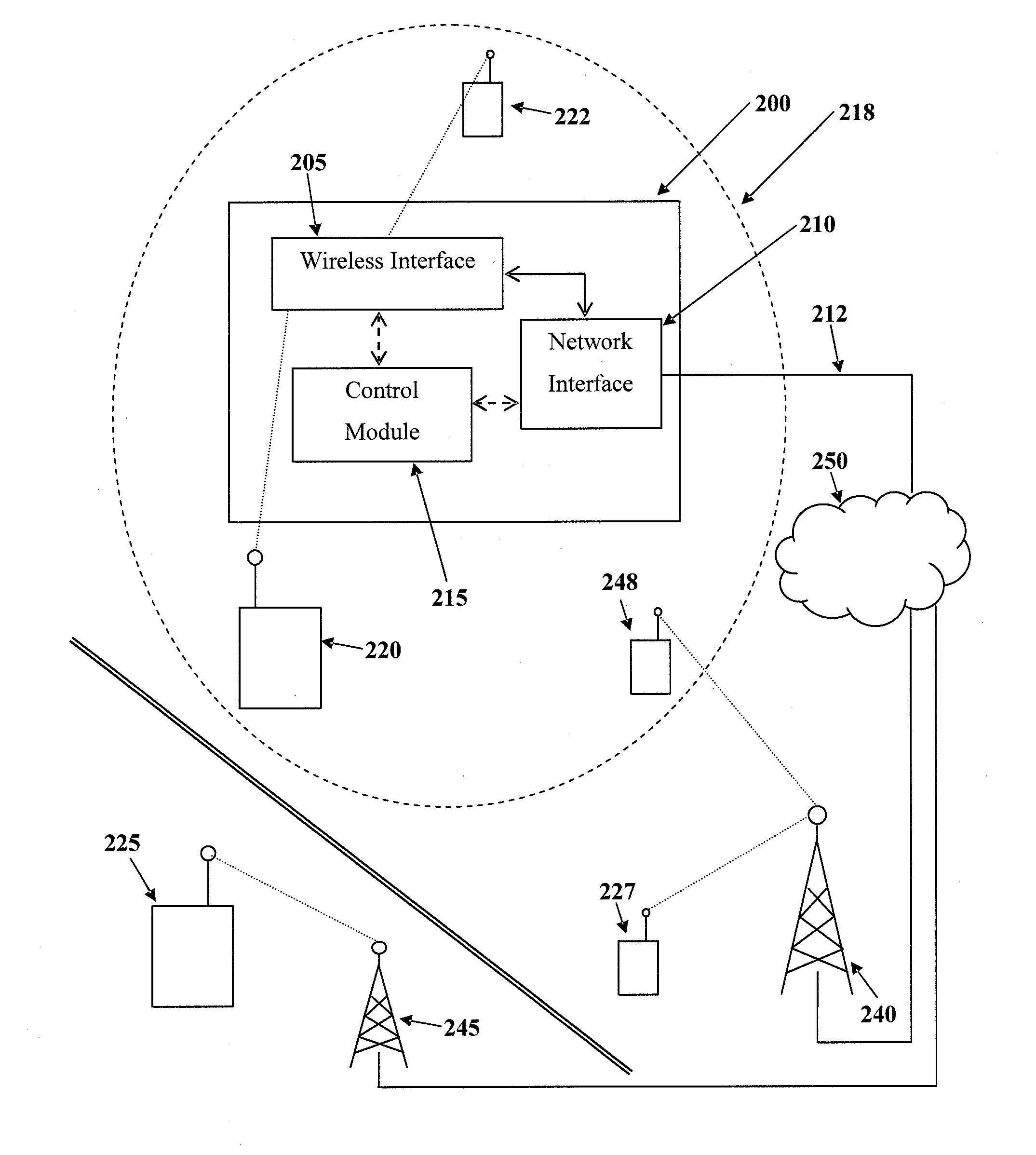
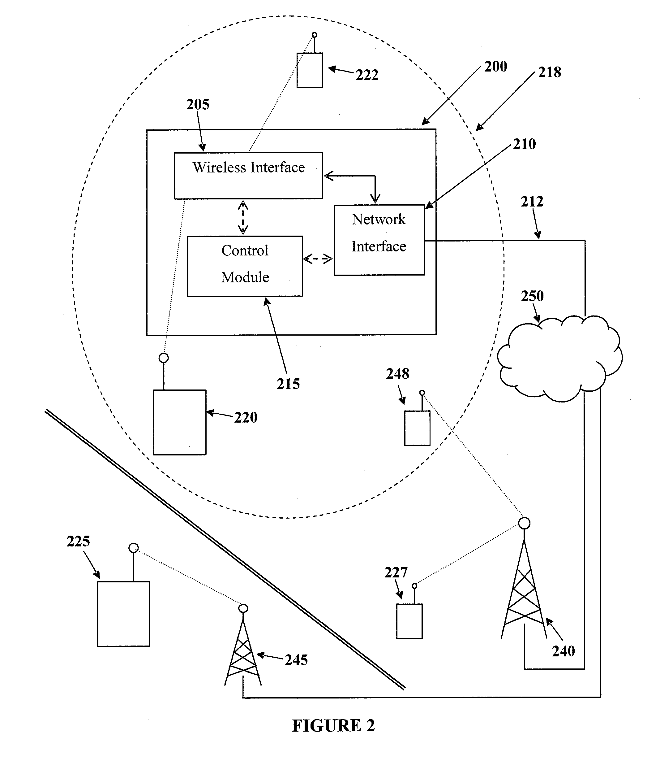
[0095]FIG. 6 illustrates a femtocell 600 operatively coupled to an auxiliary device 625 residing in a network operator's core network 620 via a network interface 603 of the femtocell 600 in accordance with embodiments of the present invention. The auxiliary device may be a server or other computing device, and may incorporate or be operatively coupled to a database 627. The database 627 is configured to track current locations of designated wireless devices, such as wireless device 640. The database 627 may be responsive to queries generated by the auxiliary device 625. The auxiliary device 625 may generate queries autonomously in accordance with a predetermined schedule, and / or receive and forward queries generated by the femtocell 600.

[0096]In some embodiments, the auxiliary device 625 may be configured to generate and transmit alert messages to the femtocell 600. For example an alert message may be generated in response to a predetermined condition of the database 627 indicative ...


PUM


Abstract

The present invention provides a method and apparatus for operating a femtocell base station of a wireless communication system. A method of the present invention comprises obtaining a list of designated wireless devices capable of communication with the base station; counting the number of designated wireless devices currently within range of the base station; and switching the base station between an active state and a standby state based on the count. The base station may obtain information for counting wireless devices currently within range by monitoring the wireless environment, and / or by monitoring information received through a network interface.

Description

FIELD OF THE INVENTION[0001]The present invention pertains in general to wireless communications and in particular to methods, apparatus and computer program products related to operation of a femtocell base station.BACKGROUND[0002]Femtocell is a technology that allows users of wireless devices, such as cell phones, PDAs, laptops equipped with cellular communications capabilities, or the like, to install small base stations in the indoor environment using licensed spectrum in order to increase coverage and / or throughput. Femtocells may provide access between a wireless device and a mobile network operator (MNO) core network. For example, the femtocell may be coupled to the operator core network through the Internet. Femtocell base stations may be installed by customers of MNOs on the customer's premises. Aspects such as energy consumption and electromagnetic emission may therefore be important factors for customer acceptance of femtocell products. FIG. 1 illustrates a femtocell base...

Claims


Application Information

Patent Timeline
Patent Type & Authority Applications(United States)
IPC IPC(8): H04W8/00
CPCH04W24/02H04W84/045H04W52/0206Y02D30/70
Inventor WU, HUAMING
Owner SEMTECH CORP
Why Eureka
Try Eureka