Drive Authorization System for an Electric Drive

a technology for electric drives and authorization systems, applied in the direction of anti-theft devices, transportation and packaging, building locks, etc., can solve the problem of difficult rapid manipulation

Active Publication Date: 2012-02-16
DAIMLER AG
View PDF0 Cites 0 Cited by
  • Summary
  • Abstract
  • Description
  • Claims
  • Application Information

AI Technical Summary

Benefits of technology

[0012]In a preferred embodiment of the drive authorization system according to the invention, the angle of rotation sensors are embodied as Hall effect sensors. In addition, the rotor has a rotor shaft wh

Problems solved by technology

A further advantage is that the rotation angle sensors, in the technical embodiment in the electric drive of

Method used


Image

  • Drive Authorization System for an Electric Drive
  • Drive Authorization System for an Electric Drive

Examples


Embodiment Construction

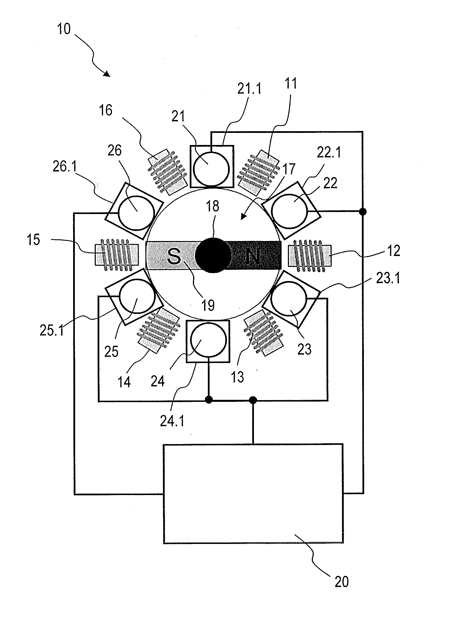
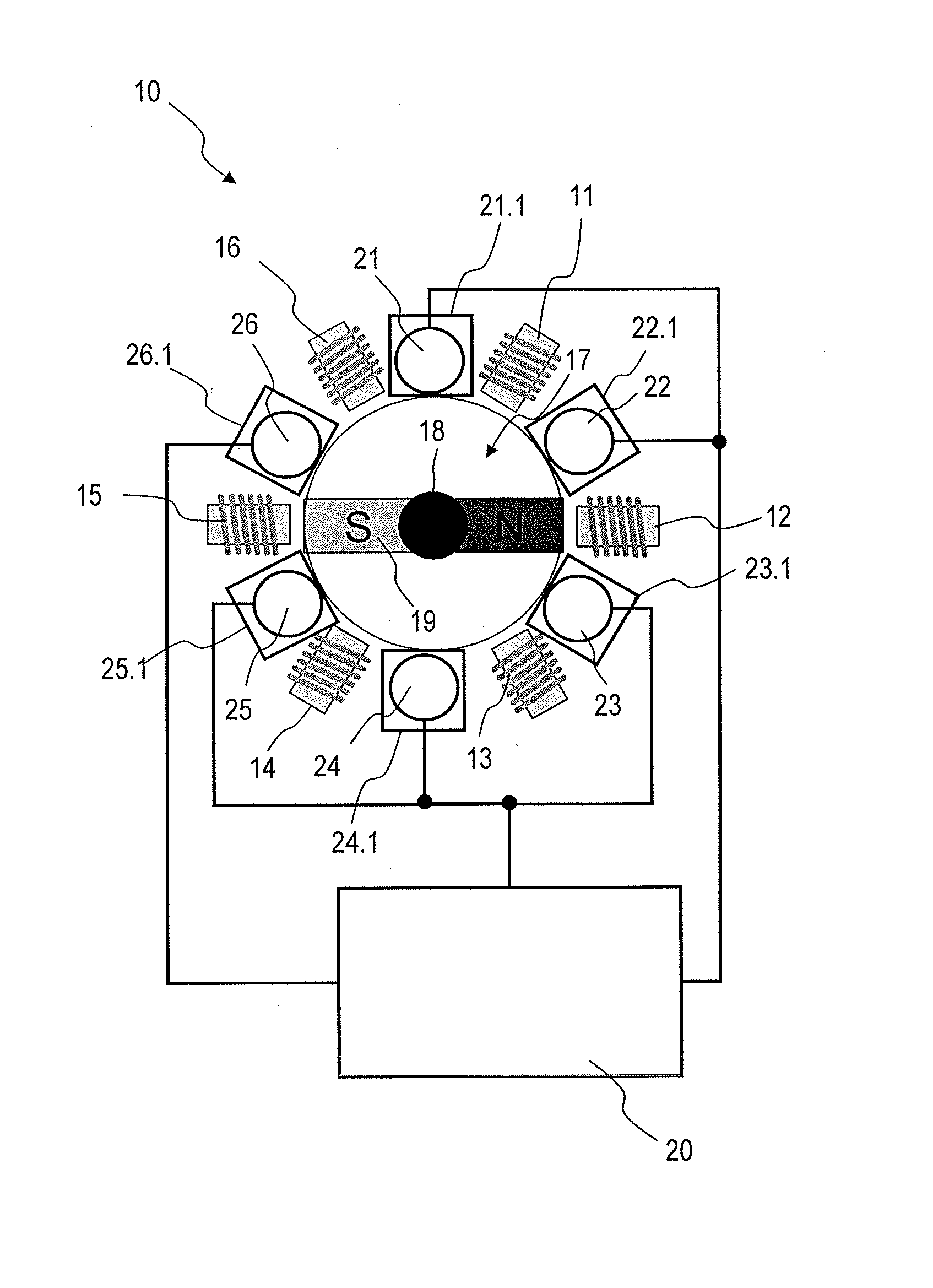
[0014]As is apparent from the FIGURE, an electric drive 10 in the embodiment illustrated comprises six field coils 11, 12, 13, 14, 15, 16 and a rotationally movable element 17, which is embodied as a rotor with a rotor shaft 18 connected to a permanent magnet 19. Between the field coils 11, 12, 13, 14, 15, 16, six possible positions 21.1, 22.1, 23.1, 24.1, 25.1, 26.1 for arranging rotation angle sensors 21, 22, 23, 24, 25, 26 are shown. An evaluation and control unit 20 for the operation of the electric drive 10 determines a current position of the movable element 17 from several items of positional information which are made available by a predefined number of angle of rotation sensors 21, 22, 23, 24, 25, 26. To implement an electronic immobilization function, the positions 21.1, 22.1, 23.1, 24.1, 25.1, 26.1 and / or the number of the active angle of rotation sensors 21, 22, 23, 24, 25, 26 are / is made encodable, and the evaluation and control unit 20 decodes the encoded positional in...


PUM


Abstract

A drive authorization system for an electric drive includes a predefined number of field coils and a rotationally movable element. An evaluation and control unit for operation of the electric drive determines the current position of the movable element from several items of positional information, which can be made available by a predefined number of angle of rotation sensors. To implement an electronic immobilization function, positions, the number of the active rotation angle sensors, or both those positions and that number are made encodable. The evaluation and control unit decodes the encoded positional information of the active rotation angle sensors in order to determine the current position of the movable element. Operation of the electric drive is possible only after successful decoding of the positional information.

Description

BACKGROUND AND SUMMARY OF THE INVENTION[0001]This invention relates to a drive authorization system for an electric drive.[0002]With conventional drive authorization systems, it is possible to circumvent an electronic immobilization function by exchanging components, e.g. control units, which are involved in the drive authorization system. For this reason, in order to increase security, an electronic immobilization function can be coupled mechatronically to a sensor system or actuator system which is difficult to access on the internal combustion engine.[0003]German Patent specification DE 43 36 212 C2 describes a sensor arrangement for detecting cylinders in an internal combustion engine. The sensor arrangement described comprises an encoder disc for detecting a defined position of a crankshaft of an internal combustion engine, a reference mark arranged on the encoder disc, a detector associated with the encoder disc, and a control means which evaluates the signal of the detector. ...

Claims


Application Information

Patent Timeline
IPC IPC(8): B60R25/04
CPCB60R25/04
Inventor KRUEGER, ANDREASSUBILEAU, SYLVAINVON HASSELN, HERMANN
Owner DAIMLER AG
Why Eureka
Try Eureka