Eureka AIR delivers breakthrough ideas for toughest innovation challenges, trusted by R&D personnel around the world.

Determining Light Level Variation in Compressive Imaging by Injecting Calibration Patterns into Pattern Sequence

a technology of compressive imaging and calibration pattern, applied in the field of compressive sensing, can solve the problems of large number of samples generated, overwhelming data volume, and reconstruction may not be satisfactory,

Inactive Publication Date: 2012-02-16
INVIEW TECH CORP
View PDF16 Cites 37 Cited by
  • Summary
  • Abstract
  • Description
  • Claims
  • Application Information

AI Technical Summary

Benefits of technology

[0030]In yet another embodiment, the compressive imaging measurements may be high-pass filtered in order to remove (or decrease or attenuate) the effect of background light variation from the compressive imaging measurements.

Problems solved by technology

A fundamental problem with any attempt to capture a signal x(t) according to Nyquist theory is the large number of samples that are generated, especially when B (or B-A) is large.
The same problem of overwhelming data volume is experienced when attempting to capture an image according to Nyquist theory.
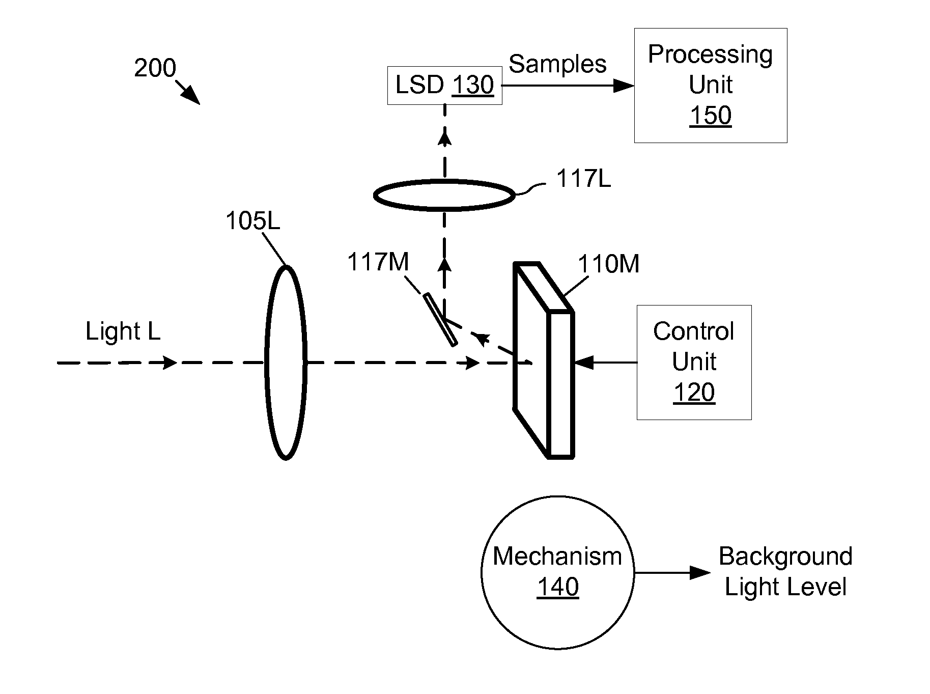
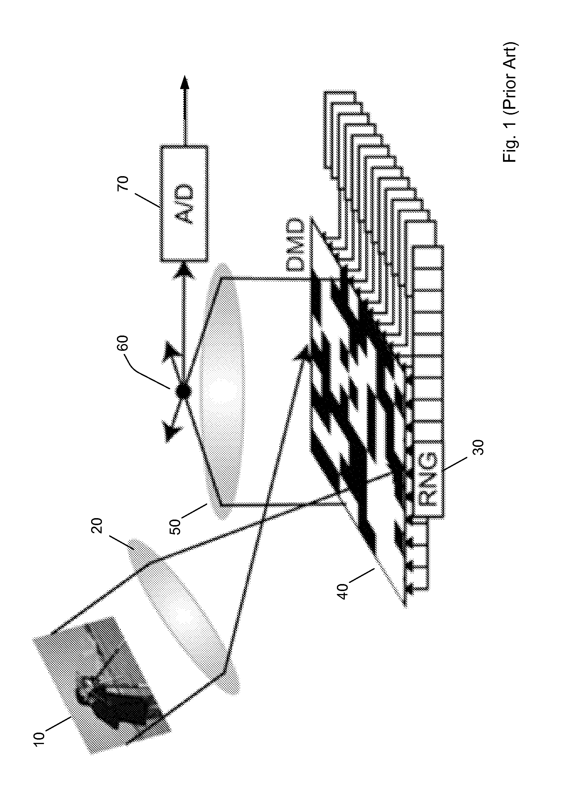
One fundamental challenge with the imaging device of FIG. 1 is that the background light level (i.e., ambient illumination level) may vary during the time interval over which the series of measurements {s(i)} is being captured.
If one attempts to reconstruct the image based on the measurements {s(i)} under the assumption that the background light level was constant, then the reconstruction may give less than satisfactory results.

Method used


Image

  • Determining Light Level Variation in Compressive Imaging by Injecting Calibration Patterns into Pattern Sequence
  • Determining Light Level Variation in Compressive Imaging by Injecting Calibration Patterns into Pattern Sequence
  • Determining Light Level Variation in Compressive Imaging by Injecting Calibration Patterns into Pattern Sequence

Examples


Embodiment Construction

[0087]The following patent applications provide teachings regarding compressive sensing and compressive imaging:

[0088]U.S. Provisional Application No. 60 / 673,364 entitled “Method and Apparatus for Optical Image Compression,” filed on Apr. 21, 2005;

[0089]U.S. Provisional Application No. 60 / 679,237 entitled “Method and Apparatus for Reconstructing Data from Multiple Sources,” filed on May 10, 2005;

[0090]U.S. Provisional Application No. 60 / 729,983 entitled “Random Filters for Compressive Sampling and Reconstruction,” filed on Oct. 25, 2005;

[0091]U.S. Provisional Application No. 60 / 732,374 entitled “Method and Apparatus for Compressive Sensing for Analog-to-Information Conversion,” filed on Nov. 1, 2005;

[0092]U.S. Provisional Application No. 60 / 735,616 entitled “Method and Apparatus for Distributed Compressed Sensing,” filed on Nov. 10, 2005;

[0093]U.S. Provisional Application No. 60 / 759,394 entitled “Sudocodes: Efficient Compressive Sampling Algorithms for Sparse Signals,” filed on Jan....


PUM


Abstract

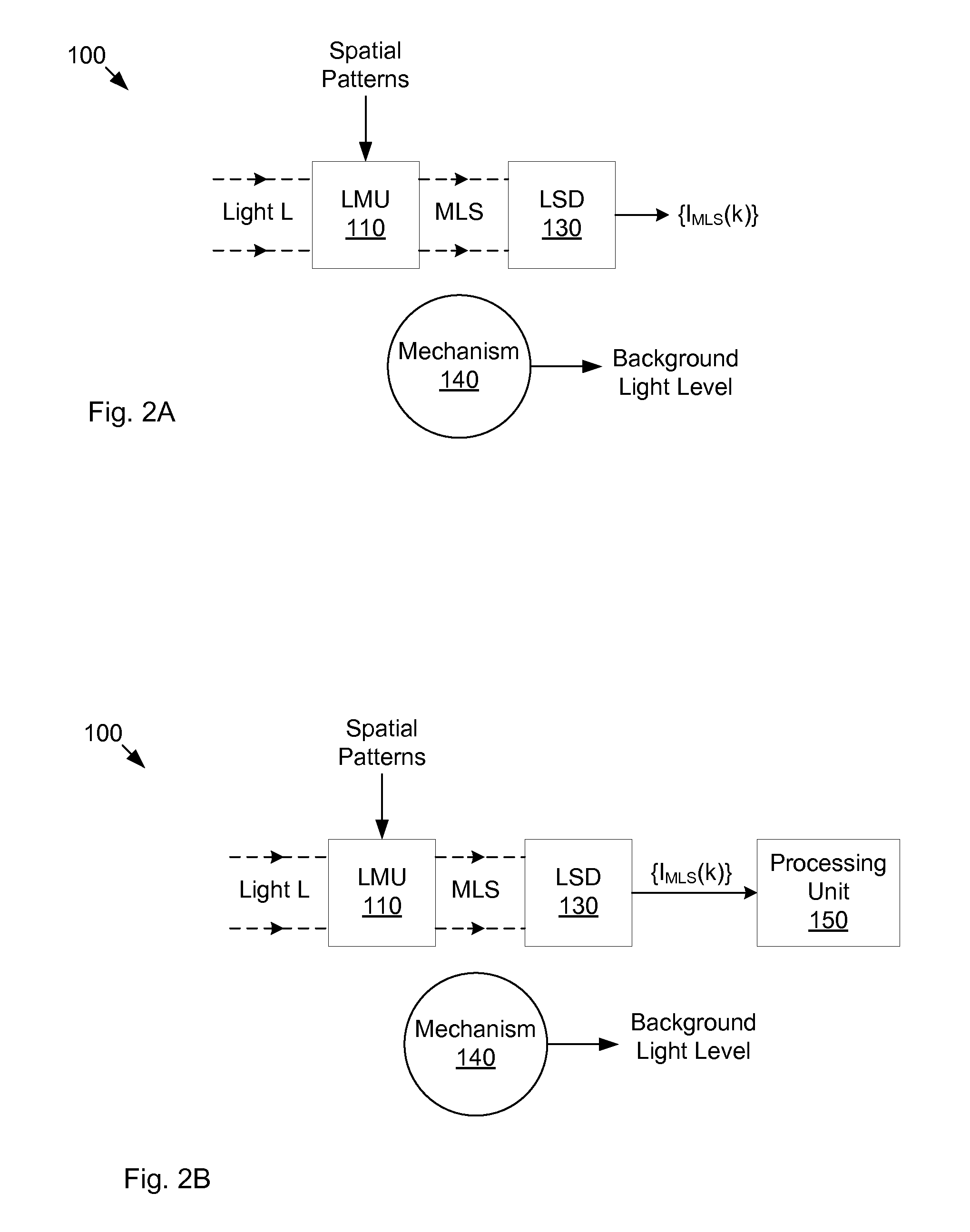
An imaging system and method that captures compressive sensing (CS) measurements of a received light stream, and also obtains samples of background light level (BGLL). The BGLL samples may be used to compensate the CS measurements for variations in the BGLL. The system includes: a light modulator to spatially modulate the received light stream with spatial patterns, and a lens to concentrate the modulated light stream onto a light detector. The samples of BGLL may be obtained in various ways: (a) injecting calibration patterns among the spatial patterns; (b) measuring complementary light reflected by digital micromirrors onto a secondary output path; (c) separating and measuring a portion of light from the optical input path; (d) low-pass filtering the CS measurements; and (e) employing a light power meter with its own separate input path. Also, the CS measurements may be high-pass filtered to attenuate background light variation.

Description

RELATED APPLICATION DATA[0001]This application claims the benefit of priority to U.S. Provisional Application No. 61 / 372,826, filed on Aug. 11, 2010, entitled “Compressive Sensing Systems and Methods”, invented by Richard Baraniuk, Gary Woods, Kevin Kelly, Robert Bridge, Sujoy Chatterjee and Lenore McMackin, which is hereby incorporated by reference in its entirety as though fully and completely set forth herein.FIELD OF THE INVENTION[0002]The present invention relates to the field of compressive sensing, and more particularly to systems and methods for determining the variation of background light level during the capture of image / video information using compressive sensing hardware.DESCRIPTION OF THE RELATED ART[0003]According to Nyquist theory, a signal x(t) whose signal energy is supported on the frequency interval [−B,B] may be reconstructed from samples {x(nT)} of the signal x(t), provided the rate fS=1 / TS at which the samples are captured is sufficiently high, i.e., provided ...

Claims


Application Information

Patent Timeline
Patent Type & Authority Applications(United States)
IPC IPC(8): H04N9/73H04N23/16H04N25/00H04N23/40H04N23/75
CPCG02B26/0833H04N5/335H04N5/238H04N5/2351H04N5/2354H04N25/00H04N23/75H04N23/71H04N23/74
Inventor KELLY, KEVIN F.BARANIUK, RICHARD G.MCMACKIN, LENOREBRIDGE, ROBERT F.CHATTERJEE, SUJOYHEWITT, DONNA E.WESTON, TYLER H.
Owner INVIEW TECH CORP
Why Eureka
Eureka Blog
Learn More