Luminaire with distributed LED sources

a technology of led sources and led lamps, which is applied in the direction of semiconductor devices, light sources, lighting and heating apparatus, etc., can solve the problems of very energy-inefficient incandescent lights, relatively inefficient leds, and significantly longer operational life of leds

Active Publication Date: 2012-02-16
IDEAL IND LIGHTING LLC
View PDF6 Cites 75 Cited by
  • Summary
  • Abstract
  • Description
  • Claims
  • Application Information

AI Technical Summary

Problems solved by technology

Incandescent lights are very energy-inefficient light sources with approximately ninety percent of the electricity they consume being released as heat rather than light.
Fluorescent light bulbs are more energy efficient than incandescent light bulbs by a factor of about 10, but are still relatively inefficient.
In addition, LEDs can have a significantly longer operational lifetime.
Incandescent light bulbs have relatively short lifetimes, with some having a lifetime in the range of about 750-1000 hours.
Fluorescent bulbs can also have lifetimes longer than incandescent bulbs such as in the range of approximately 10,000-20,000 hours, but provide less desirable color reproduction.
Because of the physical arrangement of the various source elements, multicolor sources often cast shadows with color separation and provide an output with poor color uniformity.
Thus, one challenge associated with multicolor light sources is good spatial color mixing over the entire range of viewing angles.
Uniformity typically improves with an increasing number of bounces, but each bounce has an associated optical loss.
Many of these devices are lossy and, thus, improve the color uniformity at the expense of the optical efficiency of the device.
Typical direct view lamps, which are known in the art, emit both uncontrolled and controlled light.
Uncontrolled light is light that is directly emitted from the lamp without any reflective bounces to guide it.
One design challenge associated with multi-source luminaires is blending the light from LED sources within the luminaire so that the individual sources are not visible to an observer.
However, transmission through such heavily diffusive materials causes significant optical loss.
High power LEDs can draw large currents, generating significant amounts of heat that must be managed.
Some applications rely on cooling techniques such as heat pipes which can be complicated and expensive.

Method used


Image

  • Luminaire with distributed LED sources
  • Luminaire with distributed LED sources
  • Luminaire with distributed LED sources

Examples


Embodiment Construction

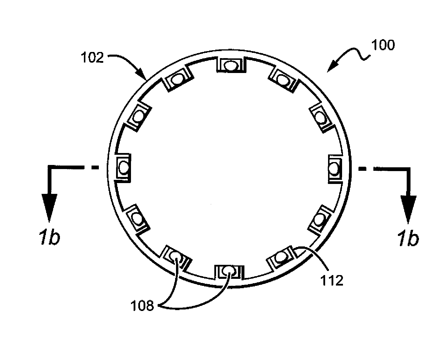
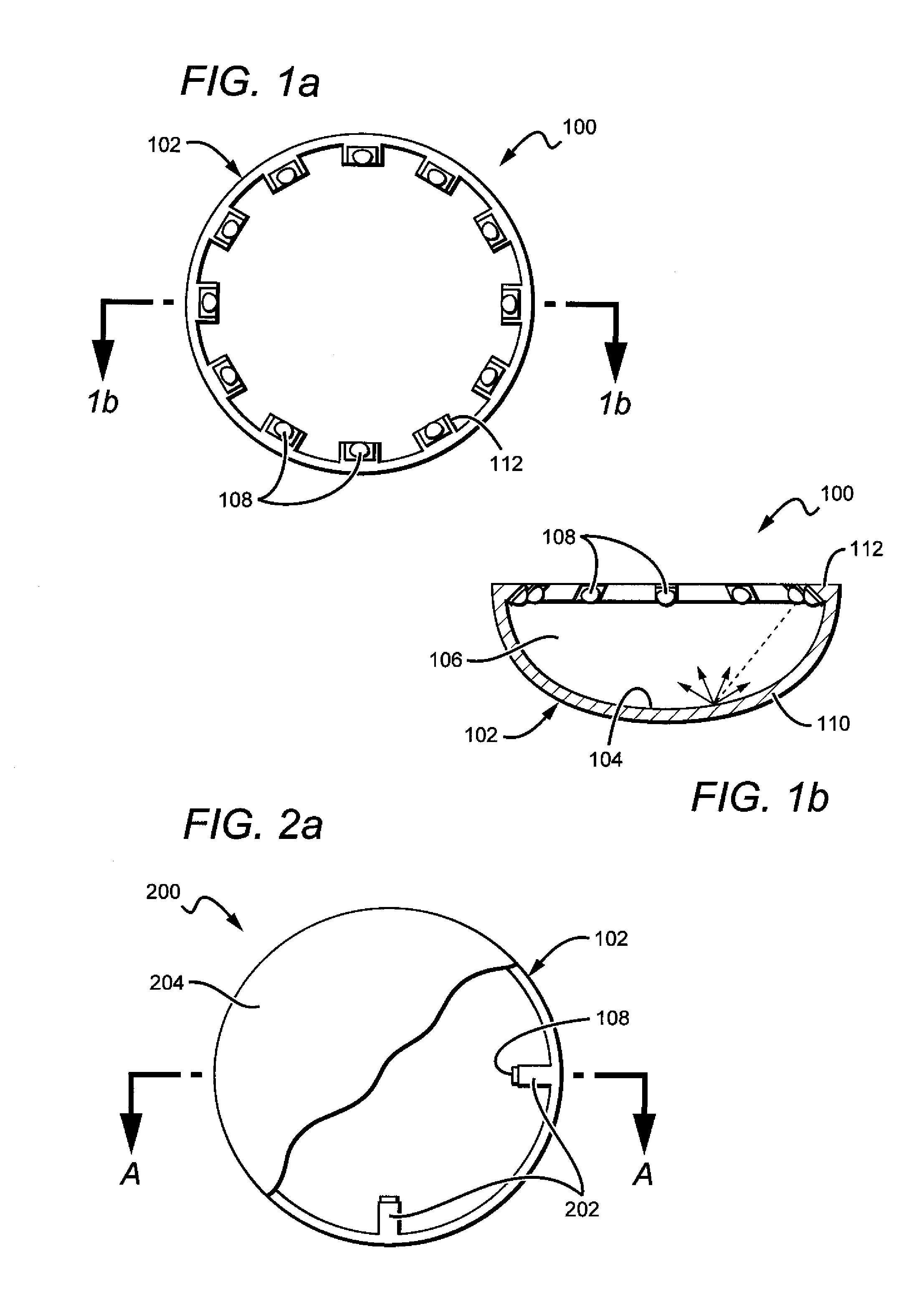
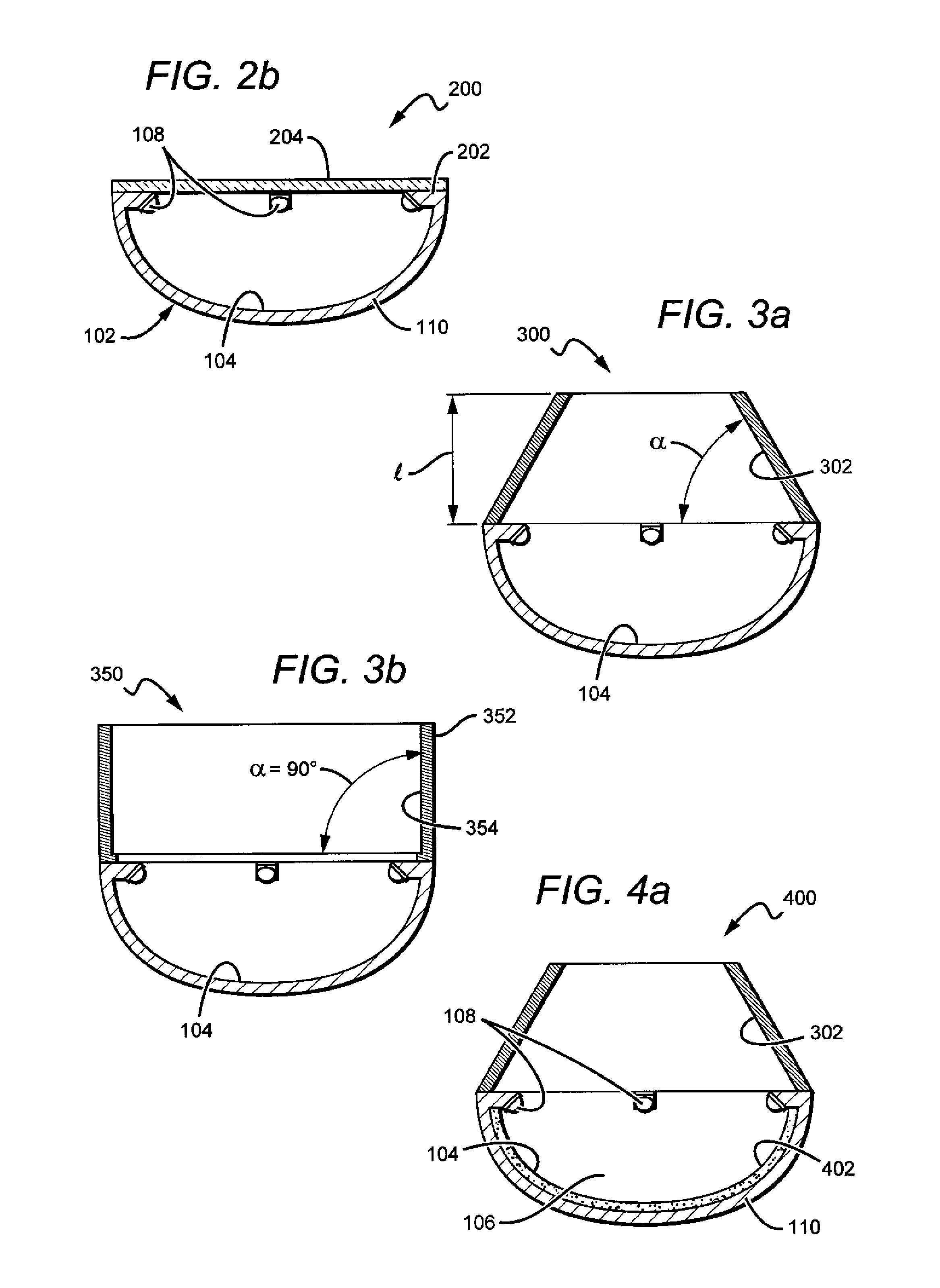
[0036]Embodiments of the present invention provide a wide beam angle (diffuse) luminaire designed to accommodate an efficient multi-source radiative emitter array. One such radiative source is a light emitting diode (LED) which will be referred to throughout the specification, although it is understood that emitters emitting outside the visible spectrum (e.g., ultraviolet or infrared emitters) and other types of radiative sources might also be used. Embodiments of the luminaire utilize one or more LEDs disposed around a perimeter of a protective casing. The LEDs are angled to emit into an internal cavity defined by the inner surface of the casing. The placement of the LEDs around the perimeter of the device reduces blocking associated with center-mount luminaire models and facilitates heat transfer from the LEDs through the casing or another heat sink and into the ambient. Light impinges on the inner surface and is redirected as useful emission from the lamp. A reflective coating ma...


PUM


Abstract

A wide beam angle (diffuse) luminaire with an efficient multi-source radiative emitter array. Embodiments of the luminaire utilize one or more LEDs disposed around a perimeter of a protective casing. The LEDs are angled to emit into an internal cavity defined by the inner surface of the casing. The placement of the LEDs around the perimeter of the device reduces self-blocking and facilitates heat transfer from the LEDs through the casing or another heat sink and into the ambient. Light impinges on the inner surface and is redirected as useful emission. A diffuse reflective coating may be deposited on the inner surface to mix the light before it is emitted.

Description

BACKGROUND OF THE INVENTION[0001]1. Field of the Invention[0002]The present invention relates to luminaire devices for lighting applications and, more particularly, to luminaires having distributed LED sources.[0003]2. Description of the Related Art[0004]Light emitting diodes (LEDs) are solid state devices that convert electric energy to light and generally comprise one or more active regions of semiconductor material interposed between oppositely doped semiconductor layers. When a bias is applied across the doped layers, holes and electrons are injected into the active region where they recombine to generate light. Light is produced in the active region and emitted from surfaces of the LED.[0005]LEDs have certain characteristics that make them desirable for many lighting applications that were previously the realm of incandescent or fluorescent lights. Incandescent lights are very energy-inefficient light sources with approximately ninety percent of the electricity they consume bei...

Claims


Application Information

Patent Timeline
Patent Type & Authority Applications(United States)
IPC IPC(8): F21V7/00F21V3/04F21V29/00F21V21/00
CPCF21V7/0008F21Y2115/10
Inventor TONG, TAO
Owner IDEAL IND LIGHTING LLC
Why Eureka
Try Eureka