Multi-purpose external rear-view mirror unit for vehicles

a rearview mirror and multi-functional technology, applied in optical viewing, lighting and heating apparatus, transportation and packaging, etc., can solve the problems of slow and costly, complicated welding of curved pieces, etc., to improve the luminous contrast, assembly and testing savings, and the effect of improving the perception of the vehicl

Active Publication Date: 2012-02-16
RODRIGUEZ BARROS ALEJANDRO
View PDF5 Cites 21 Cited by
  • Summary
  • Abstract
  • Description
  • Claims
  • Application Information

AI Technical Summary

Benefits of technology

[0033]Said opaque wall interpolated between both luminous devices is generally a structural opaque part of the rear-view mirror (casing cover or supplementary cover); it behaves like a protective area against impacts and scratches, so said structural part or cover is preferably made of an extra hard material (aluminium or carbon fibre, ASA, resins, ABS or polycarbonate, among others); in addition, it allows to improve the luminous contrast relative to the incidence of external beams in daytime by hiding the electro-optical interface, which comprises a selection among: the light source, optical arrangements, reflectors, LEDs, circuits, intermediate optics, light guides, collimators, reflectors, parabolas.
[0034]The independence between said first and second devices allows for the addition of other signals and functions that are secured to the structures containing them—for instance, the wing frame—or to one of said closures of the outside cover, forming subsets or sets of associated parts and / or for the association of new functions in one same device or subset by adding emitters and various light outputs that share their electro-optical interface, which entails assembly and testing savings, since they are effected in one single operation.
[0035]In an embodiment, said first device is secured and integrated into the wing frame by means of an internal body of its electro-optical interface. The forward orientation of the frame allows for the addition of visible functions visible by the driver as control, telltale and / or welcoming lights.
[0036]In an embodiment, the orientation of the outside cover towards the front-side, allows for the addition of location signals so as to have a better perception of the vehicle as seen from the side or the front at daytime or night-time and, in another example, said devices or frontal cover include a complementary viewing camera facing the front and downwards (preferably aimed at the front wheel on the opposite side of the driver), wherein the blinking device, with its light source, assists and facilitates the operation of said camera.

Problems solved by technology

Said blinking devices are curved and elongated, which entails problems such as:Moulds of curved, elongated pieces have a complicated, costly demoulding.They are unstable, become deformed and it is difficult to make them match in the overall assembly.Welding curved pieces together is complicated, slow and costly.The protrusion of the transparent cover matches the lateral protruding area of the vehicle liable to receive collisions.Each rear-view mirror has a different external curve and shape, which prevents the standardisation of pieces so that they will be used in various vehicles and implies longer time for their development, higher cost of the moulds and more pieces and tools.
As they are interconnected, cables and limited mobility are also a problem.

Method used


Image

  • Multi-purpose external rear-view mirror unit for vehicles
  • Multi-purpose external rear-view mirror unit for vehicles
  • Multi-purpose external rear-view mirror unit for vehicles

Examples


first embodiment

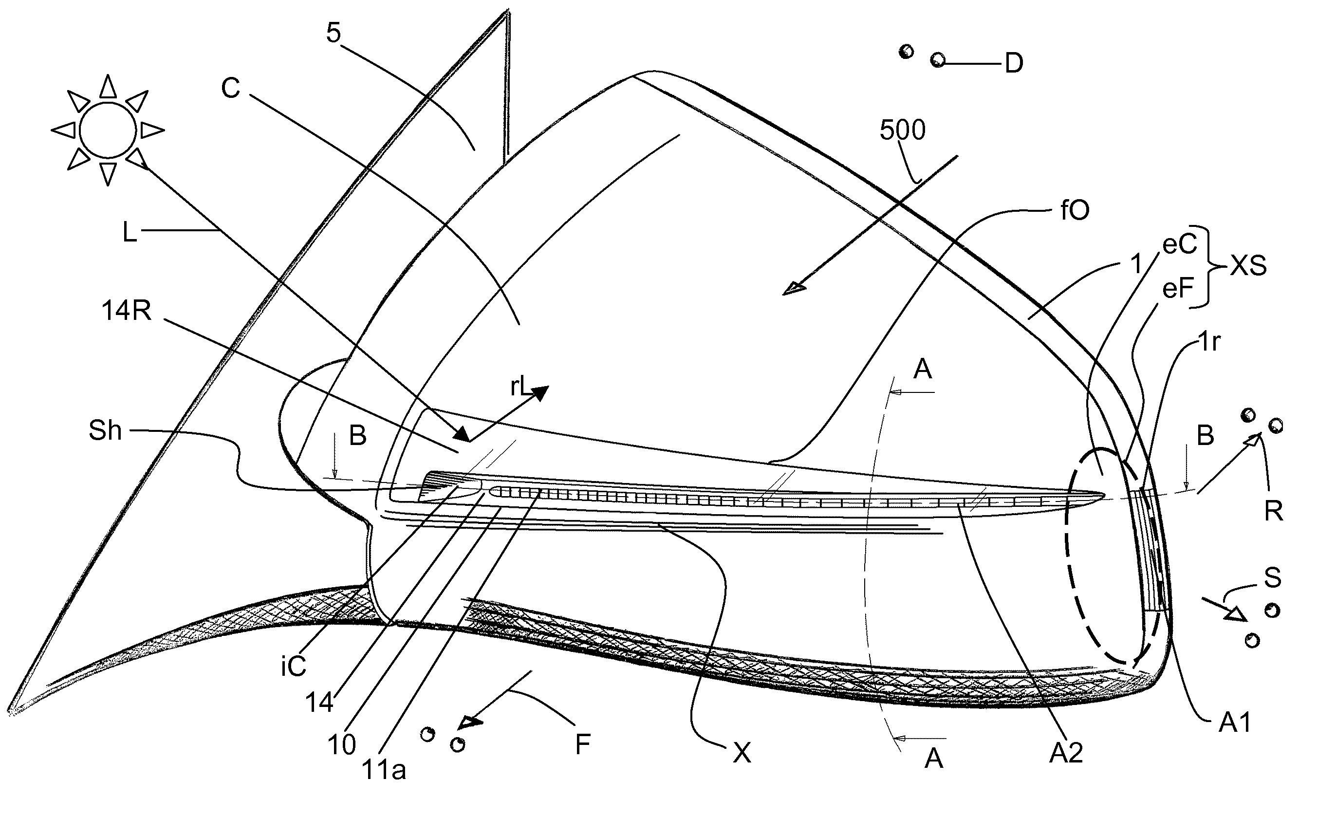
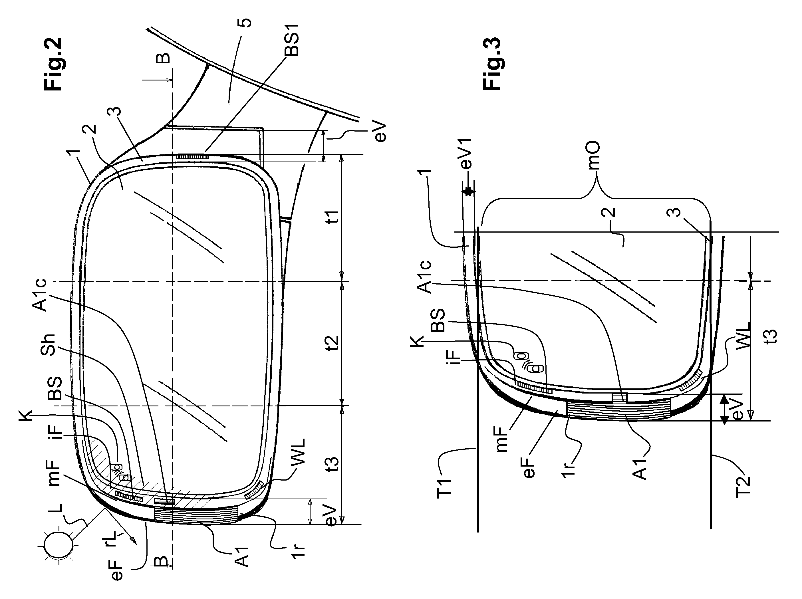
[0157]In a first embodiment, said internal duct iC has a reflective face surface 14 or at least one piece associated to said supporting body 13 which forms a reflective face surface 14 (depending on the case, including one piece to part of the supporting body is preferred to facilitate the metallisation and welding processes) and it has reflective means selectable among facets or associated micro mirrors 14f, a collimator, an etching, or it is plain, metallised, plated, painted or of a material of any colour, even white.

[0158]Said internal duct iC is, at least in part, of black or dark colour and it has a surface 14 of any colour and antireflective texture, even in an embodiment including, in addition, reflective means such as a metallised collimator and a light guide 11.

second embodiment

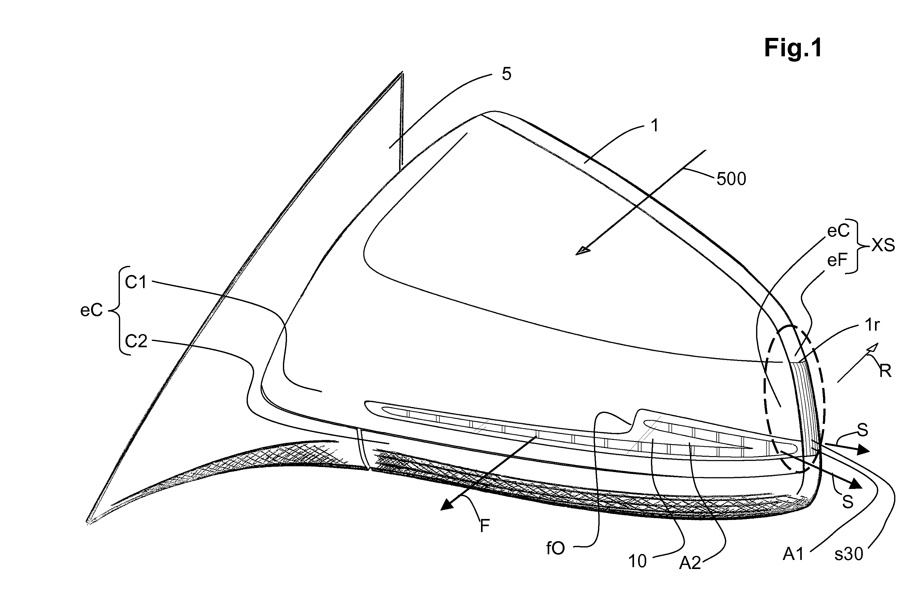
[0159]In a second embodiment, the device A2 has, in its interior duct, an elongated transparent optical body 11, protected and substantially parallel relative to the transparent external surface 10, with at least one light input 11i associated and matching the optically coupled light input 9i being emitted from the first device A1 of frame 1.

[0160]Said elongated optical body 11 is a light guide 11 with any sectional profile, producing an internal axial reflection 22r, for which it has several means, a series of prisms, facets 14r, arranged in a gradual, regular, even manner, with calculated inclination and separation, or with nanometric proportions, etchings and / or reflective paint or film, depending on how said reflection is intended to be faced; said means being arranged on a track 12 at the same or different level than the internal adjacent surface of the guide 11 depending on the distribution of the light to be reflected and in order not to break the tangentiality of said light ...

third embodiment

[0162]In a third embodiment, said casing device A2 exhibits version A2b, which has a light guide 11b that is embedded or overinjected sharing the mould with said transparent external element 10. This way, if the overinjection is effected in two materials, a transparent external element of two colours can be obtained. For this embodiment, the light source iN of said blinking device A1 is within said external volume eV of said wing frame 1, which is a volume independent from the interior of the casing iH, since it is a thickening (a rear-view mirror wing frame is normally solid, has no thickening and would define the casing interior itself), and since said light guide, through its integration with the transparent element, occupies less volume in the outside cover, then said device A2 is liable to extend into the external volume eV of said frame 1.

[0163]Other embodiments and building method present a device A2a that has a light guide 11a and a transparent external element 10, which for...


PUM


Abstract

A kitchen container make of flexible material (such as a silicone elastomer) for culinary applications. The flexible material is capable of being deformed into different positions befitting different uses, in particular cooking in a microwave and in a conventional oven. Opposite openings separated by portions of two sides of a perimetric wall of the kitchen container facilitate air circulation and partial retention of vapours while cooking.

Description

FIELD OF THE ART[0001]The present invention relates in general to a multifunction wing rear-view mirror for vehicles adapted to emit at least one turning signal in three directions—forwards, to the side and rearwards—and, in particular, to a rear-view mirror arrangement made up by an outside cover, a wing frame surrounding a mirror, and having, in a portion of said frame, a first luminous blinking device with its own light source, fit to emit at least one turning signal rearwards and to the side, and a second lacking its own light source and independent in construction from the first one, located in an area of said outside cover, having reflective means to emit a turning signal directed to the front of the vehicle, after receiving a conjoint beam of light from the light source of said first luminous blinking device by means of an optical coupling.STATE OF THE BACKGROUND ART[0002]A number of patents are known related to rear-view mirror arrangements with a turning signal being emitte...

Claims


Application Information

Patent Timeline
Patent Type & Authority Applications(United States)
IPC IPC(8): B60Q1/34B60Q1/24B60Q1/28B60R1/12
CPCB60Q1/2665B60R1/1207
Inventor RODRIGUEZ BARROS, ALEJANDRO
Owner RODRIGUEZ BARROS ALEJANDRO
Why Eureka
Try Eureka