Unlock instant, AI-driven research and patent intelligence for your innovation.

Oxidation state sensors and methods for transition metal alloys

a technology of oxidation state and sensors, applied in the direction of instruments, fluorescence/phosphorescence, analysis using chemical indicators, etc., can solve the problems of corrosion, high temperature and pressure conditions of alloy components, and increased degradation rate of components

Inactive Publication Date: 2012-02-16
ROLLS ROYCE PLC
View PDF4 Cites 3 Cited by
  • Summary
  • Abstract
  • Description
  • Claims
  • Application Information

AI Technical Summary

Benefits of technology

The present invention provides a method for assessing the distribution of degradation in alloy components without the need to damage or destroy the component. This method involves applying an oxidation state sensor molecule to the surface of the alloy and selectively associating with a transition metal in a different oxidation state. This allows for the determination of degradation in the alloy by analyzing the distribution of the sensor molecule on the surface. The method is non-destructive, can be used on a range of alloy components, and can be applied to large surface areas. It can also be used to extend the service life of components by identifying areas of degradation and allowing for targeted maintenance.

Problems solved by technology

In use, alloy components often experience high temperature and pressure conditions.
These conditions lead to an increased rate of degradation of the components.
Typically, degradation is caused by corrosion and oxidation.
Degradation of the component weakens and reduces the desired properties of the alloys.
Naturally, the surface of the components are often particularly susceptible to degradation.
The weakening of alloy components caused by degradation limits the lifetime of each component.
Obtaining a sample of the component to be used in such methods usually causes damage to the component, so that the component may not be used again.
In some cases, the method itself may damage the section of the alloy that is being tested.

Method used


Image

  • Oxidation state sensors and methods for transition metal alloys
  • Oxidation state sensors and methods for transition metal alloys
  • Oxidation state sensors and methods for transition metal alloys

Examples


example 1

Superalloy Rod Testing

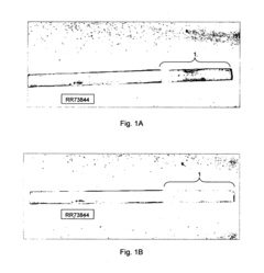
[0286]FIG. 1A shows RR73844 rod after a 1 cm portion of the rod (labelled 1) has been immersed immersion in peroxide solution for 24 hours and then the whole rod has been immersed in chemical sensor solution for 24 hours. In the figures, dark areas represent areas where fluorescence has been observed with the excitation laser and observation filter. White areas correspond to regions where no fluorescence has been observed.

[0287]The right-hand side of FIG. 1A (labelled 1) shows a darker region that correlates with exposure to peroxide. Further left a lighter region is present, which was not exposed to peroxide. FIG. 1B shows a fluorescence image of the same rod after it has been wiped with acetic acid. None of the chemical sensor remains and the oxidised region is once again invisible against the rest of the metal.

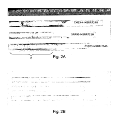
[0288]FIG. 2A shows the result from exposing superalloy rods CMSX®-4, SRR99 and C1023 to peroxide and the sensor, and imaged using an excitation laser...

example 2

Turbine Superalloy Testing

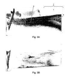
[0300]FIG. 3A shows a service-run HP (High Pressure) turbine blade from a Trent® 900 engine. The blade has been cross sectioned at points 3 and 4, in order to expose the Ni superalloy through the Pt coating. The blade was immersed in chemical sensor for 24 hours, washed with water and fluorescence imaged, as above.

[0301]A complex array of spots and dark areas are revealed by the chemical sensor, which are not visible on normal inspection. Also, there is evidence that some of the regions where the surface has been ground away have a higher fluorescence response. For comparison, FIG. 3B shows the same turbine blade using fluorescence imaging after removal of the chemical sensor with acetic acid. Very few features are visible in this image, indicating that the chemical sensor is able to selectively associate with certain areas.

[0302]From Example 1, we note that the sensor associates with transition metals in an oxidation state greater than zero. In FIG. 3A, th...


PUM

PropertyMeasurementUnit
concentrationaaaaaaaaaa
total volumeaaaaaaaaaa
absorption wavelengthaaaaaaaaaa

Abstract

The present invention is concerned with a method of discriminating between, in a surface of a transition metal alloy, transition metals in different oxidation states using surface sensor molecules adapted to associate selectively with one of the transition metals. In particular, the present invention provides a method of identifying degradation in aircraft components such as turbine blades, engine casings and aerofoils. In embodiments, a surface sensor molecule comprising an oxidation state discriminating group, such as an imidazole, and a fluorescein probe is applied in aqueous solution to the surface of a service-run Ni alloy aircraft component. The sensor molecule selectively associates with transition metals in oxidation states greater than zero such that fluorescence imaging can be used to identify areas of degradation.

Description

TECHNICAL FIELD OF THE INVENTION[0001]The present invention relates to methods of treating an alloy surface to discriminate between oxidation states of transition metals in the alloy. The present invention is also concerned with the use of a sensor for discriminating between oxidation states of transition metals, and an alloy with an oxidation state sensor molecule associated with it.BACKGROUND[0002]Alloys are used in many components of the automotive, aeronautical and nautical industries. Alloys comprise at least one metallic element and at least one other element, metallic or non-metallic. Some properties of the alloy are typically enhanced over their individual component elements, such as increased tensile strength or thermal resistance.[0003]In use, alloy components often experience high temperature and pressure conditions. These conditions lead to an increased rate of degradation of the components. Typically, degradation is caused by corrosion and oxidation. Degradation of the ...

Claims


Application Information

Patent Timeline
Patent Type & Authority Applications(United States)
IPC IPC(8): G01N33/20G01N21/76G01N21/64
CPCG01N21/643G01N31/22G01N21/91
Inventor CLARK, DANIELBURROWS, JUSTIN
Owner ROLLS ROYCE PLC