Slip-Controlled Hydraulic Vehicle Brake System

a brake system and hydraulic technology, applied in the direction of brake systems, vehicle components, brake components, etc., can solve the problems of elongation of the brake pedal actuation and failure of the brake circuit connected thereto

Inactive Publication Date: 2012-02-23
CONTINENTAL TEVES AG & CO OHG
View PDF30 Cites 16 Cited by
  • Summary
  • Abstract
  • Description
  • Claims
  • Application Information

AI Technical Summary

Problems solved by technology

It is considered to be a disadvantage of the known vehicle brake system that a leak of an outlet valve results in an elongation of the brake pedal actuating travel, wherein when the associated pressure chamber of the master brake cylinder is exhausted, the brake circuit connected thereto may fail.

Method used


Image

  • Slip-Controlled Hydraulic Vehicle Brake System
  • Slip-Controlled Hydraulic Vehicle Brake System
  • Slip-Controlled Hydraulic Vehicle Brake System

Examples


second embodiment

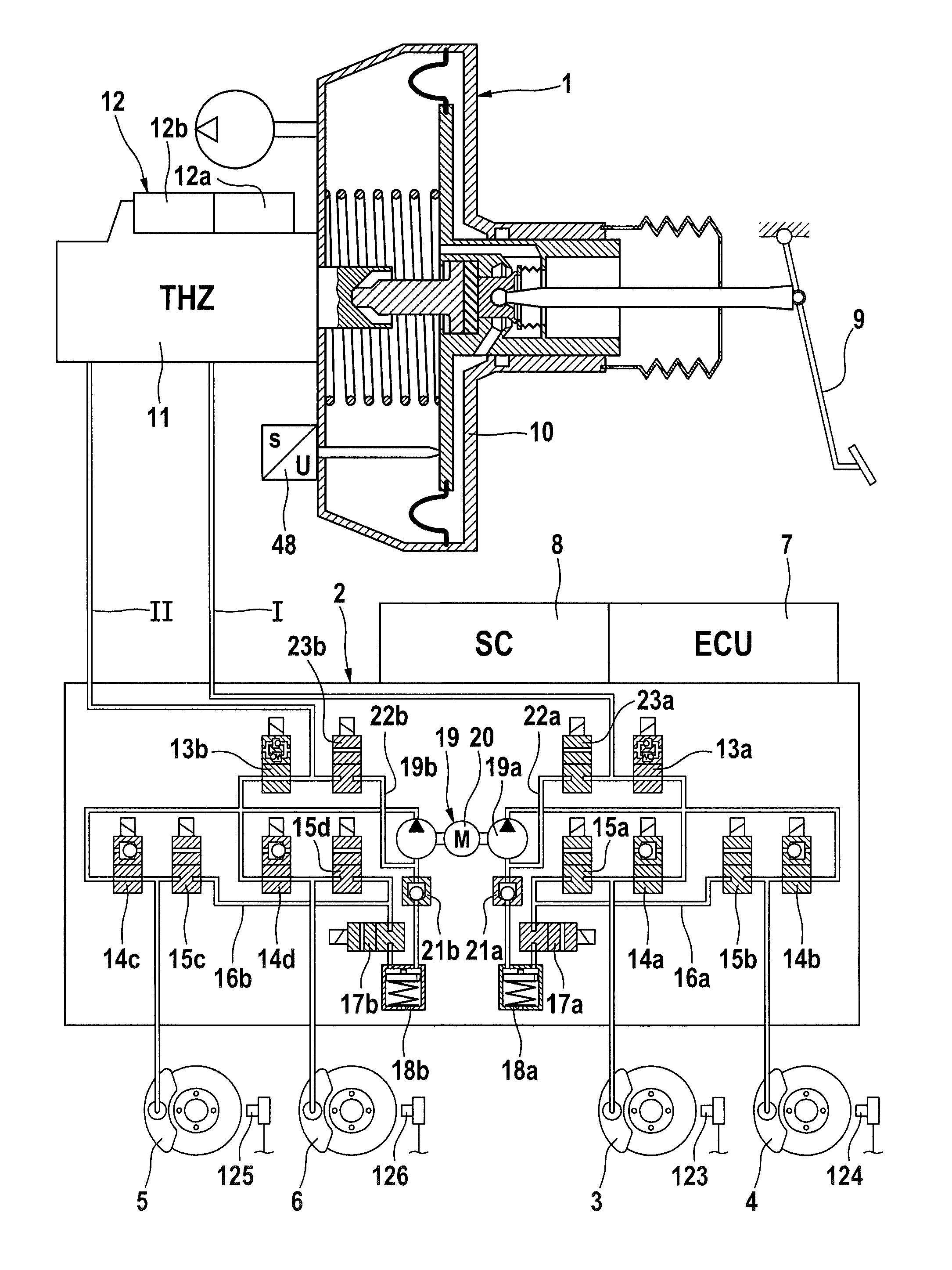
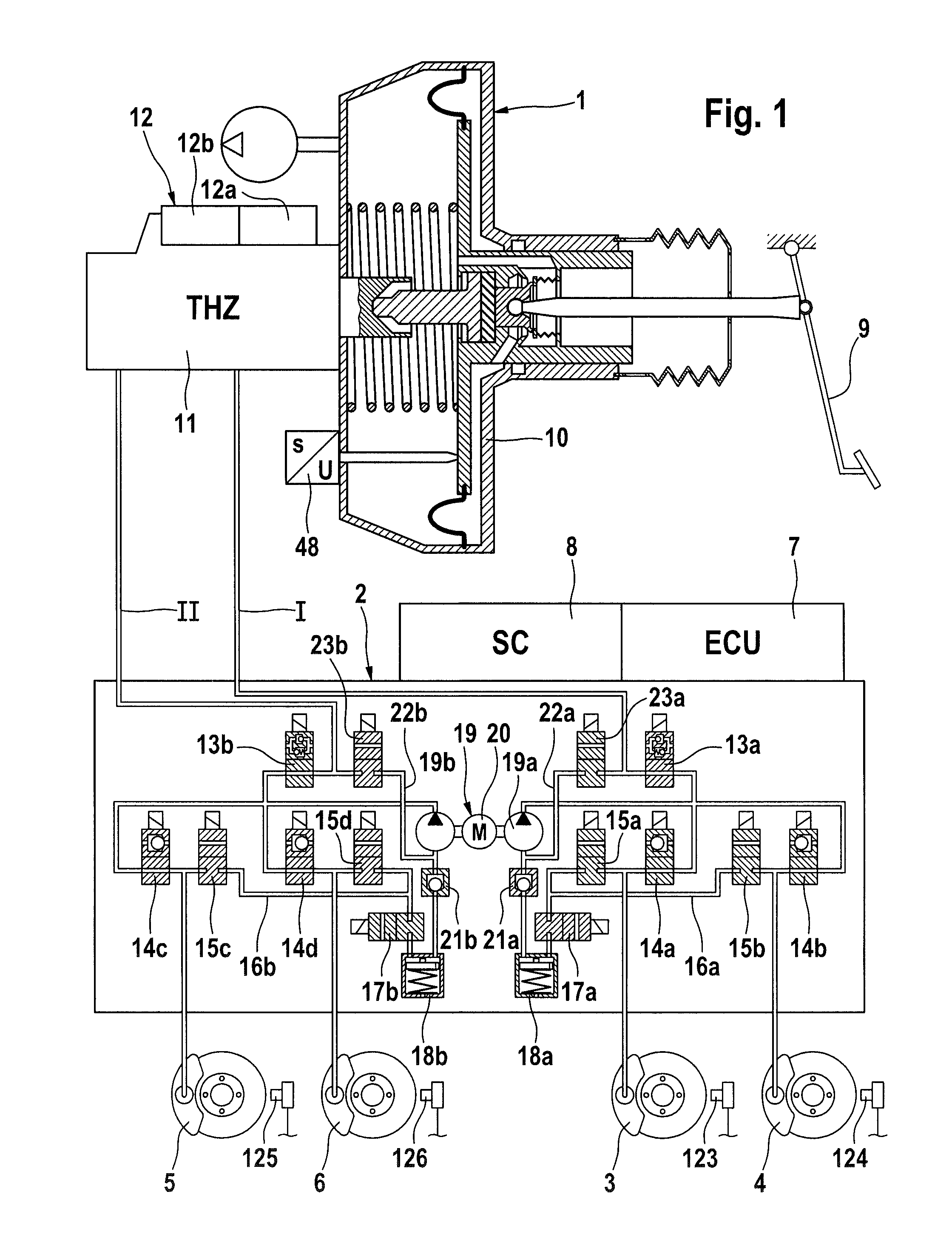
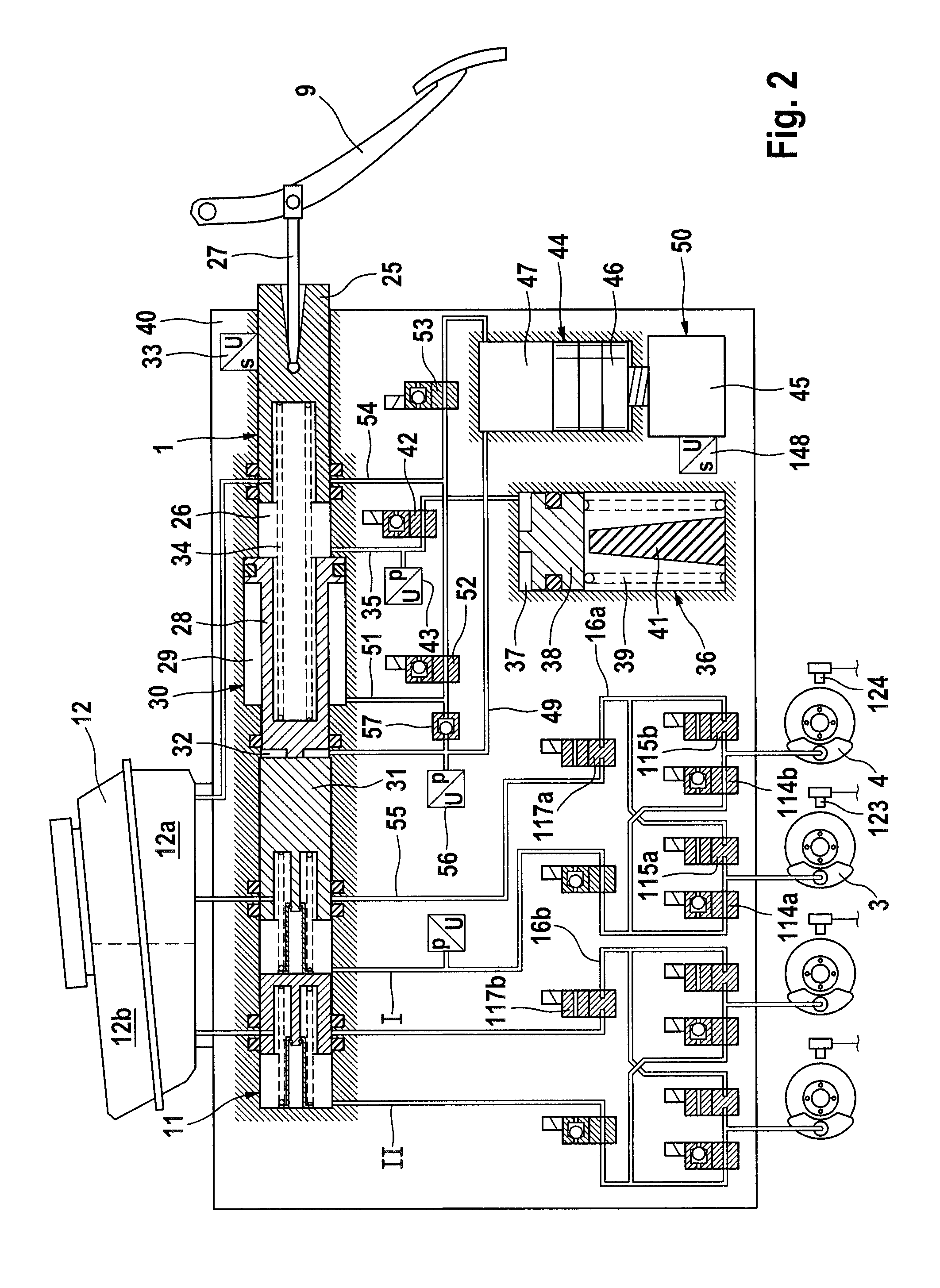
[0010]The invention will be explained in more detail below on the basis of two exemplary embodiments illustrated in the appended drawing. Here, FIGS. 1 and 2 each show a hydraulic circuit diagram of a first and a vehicle brake system according to the invention.

first embodiment

[0011]the vehicle brake system according to the invention, as shown in FIGS. 1, is provided for carrying out slip control processes, in particular anti-lock brake system (ABS), traction control (or anti-spin regulation (ASR)) and driving dynamics control (electronic stability program (ESP)). The brake system, which preferably has two brake circuits I and II consists substantially of an actuation unit 1, a wheel brake pressure modulation device 2 which is connected to the actuation unit 1, wheel brakes 3, 4, 5, 6 which are connected to the wheel brake pressure modulation device 2, and an electronic control and regulating unit (ECU) 7 assigned to the brake pressure modulation device 2. The reference numeral 8 denotes a sensor cluster (SC) which comprises the sensors required for carrying out the abovementioned regulating processes, the output signals of which sensors are supplied to the electronic control and regulating unit 7. Here, the assignment of the wheel brakes 3-6 to the brake...


PUM


Abstract

A hydraulic vehicle brake system and method of operating same. The system includes an electrohydraulic wheel brake pressure modulation unit, a master brake cylinder (11) which has a pressure medium storage reservoir (12) for hydraulic brake fluid and which can be actuated by means of a brake pedal (9) and to which first and second brake circuits (I, II) are connected. Wheel brakes (3, 4, 5, 6) are connected to the first and second brake circuits (I, II). Each of the first and second brake circuits have a pair of inlets valves (14a-d, 114a-b) and a pair of outlet valves (15a-d, 115a-b) connected to the wheel brakes (3, 4, 5, 6). The outlets of the outlet valves (15a-d, 115a-b) of each of the first and second brake circuits (I, II) are connected to one another by means of jointly used hydraulic line sections (16a, 16b). A safety valve (17a, 117a; 17b, 117b) is provided by means of which an outflow of brake fluid medium out of the line section (16a, 16b) via an outlet port of the safety valves (17a, 117a; 17b, 117b) can be monitored as a means of checking the leak-tightness of the outlet valve and the safety valve.

Description

CROSS REFERENCE TO RELATED APPLICATIONS[0001]This application claims priority to German Patent Application No. 10 2009 002 695.9, filed Apr. 28, 2009, German Patent Application No. 10 2009 045 714.3, filed Oct. 15, 2009, and PCT International Patent Application No. PCT / EP2010 / 055098, filed Apr. 19, 2010.FIELD OF THE INVENTION[0002]The present invention relates to a hydraulic vehicle brake system with slip regulation, and to a method for operating a brake system.BACKGROUND OF THE INVENTION[0003]A vehicle brake system of the above mentioned type is known for example from the international patent application WO 2008 / 017548. In the already known, preferably two-circuit brake system, a hydraulic line section which connects the outlet ports of outlet valves of a brake circuit is connected to a pressure medium storage reservoir and to the suction side of a hydraulic pump whose pressure side is connected via the inlet valves to vehicle wheel brakes.[0004]It is considered to be a disadvantag...

Claims


Application Information

Patent Timeline
Patent Type & Authority Applications(United States)
IPC IPC(8): B60T8/17B60T8/176B60T13/68B60T8/34
CPCB60T8/348B60T8/88B60T8/4872B60T8/4077B60T8/34B60T8/48B60T8/40
Inventor LINKENBACH, STEFFENJUNGBECKER, JOHANNSCHIEL, LOTHARDRUMM, STEFAN A.
Owner CONTINENTAL TEVES AG & CO OHG
Why Eureka
Try Eureka