Connecting structure for relay terminal
- Summary
- Abstract
- Description
- Claims
- Application Information
AI Technical Summary
Benefits of technology
Problems solved by technology
Method used
Image

Examples
first embodiment
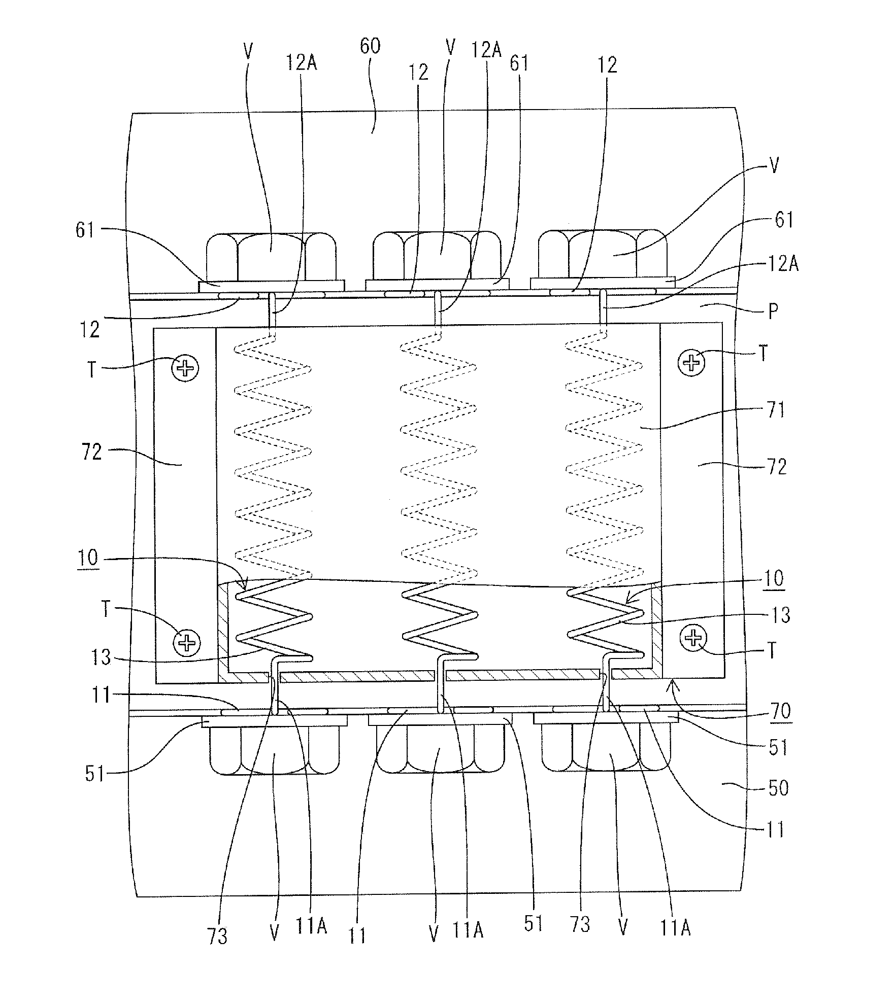
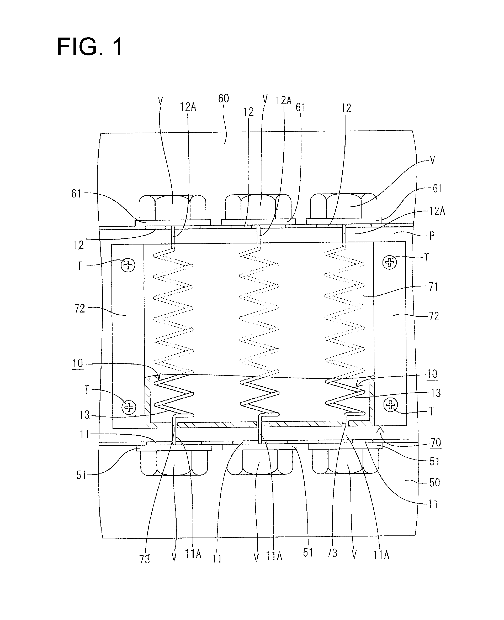
[0033]FIGS. 1 to 4 illustrate a connecting structure for relay terminals 10 that electrically connect a motor 50 fixed to an unillustrated engine and an inverter 60. The connecting structure preferably is used in a vehicle, such as a hybrid vehicle or an electric vehicle.
[0034]The motor 50 and the inverter 60 are housed in the same case (not shown) and are partitioned by an unillustrated partition wall. The motor 50 is used in the housing with a fluid for cooling (e.g. ATF) showered thereon.
[0035]The motor 50 includes three motor side terminals 51, as shown in FIGS. 1 and 4. Each motor side terminal 51 is formed with a bolt insertion hole 51A through which a fastening bolt V is insertable.
[0036]Similarly, the inverter 60 includes three inverter side terminals 61. Each inverter side terminal 61 is formed with a bolt insertion hole 61A, through which a fastening bolt V is insertable.
[0037]The relay terminals 10 are formed by bending enameled wires and, in this embodiment, three relay ...
second embodiment
[0060]The coil springs 14 of the three relay terminals 20 of the second embodiment are wound spirally together in the clockwise direction. However, the coil springs 14 of the three relay terminals 20 may be wound spirally together in the counterclockwise direction.
[0061]The coil springs 14 of the three relay terminals 20 are wound spirally together in the second embodiment. However, coil springs of more or fewer relay terminals may be wound spirally together.
[0062]The coil springs of the relay terminals are wound spirally at substantially equal pitches in the above embodiments. However, the spiral winding pitches may be irregular.
[0063]The motor side annular connecting portions 11 and the inverter side annular connecting portions 12 are fixed to the same terminal block P in the above embodiments. However, the motor side annular connecting portions 11 and the inverter side annular connecting portions 12 may be fixed respectively to different terminal blocks.
[0064]The coil springs 14 ...
PUM
 Abstract
Description
Claims
Application Information
 - Generate Ideas
- Intellectual Property
- Life Sciences
- Materials
- Tech Scout
- Unparalleled Data Quality
- Higher Quality Content
- 60% Fewer Hallucinations
Browse by: Latest US Patents, China's latest patents, Technical Efficacy Thesaurus, Application Domain, Technology Topic, Popular Technical Reports.
© 2025 PatSnap. All rights reserved.Legal|Privacy policy|Modern Slavery Act Transparency Statement|Sitemap|About US| Contact US: help@patsnap.com