Isolated switching converter

Inactive Publication Date: 2012-02-23
CUK SLOBODAN
View PDF5 Cites 32 Cited by
  • Summary
  • Abstract
  • Description
  • Claims
  • Application Information

AI Technical Summary

Benefits of technology

[0187]Yet present invention could instead of 30V rated switches, use 7.5V rated switches (with all associated advantages in reduction of losses) and/or reduction of the cost of devices or both.
[0188]The present invention could also find the application for low output voltages such as for 12V to 1V, 50A converters needed for modern microprocessors power supplies. The absence of

Problems solved by technology

The conventional switched-mode power conversion theory excludes a priory presence of inductors in the branches with the switches based on the fact that inductor current could not be interrupted without bad consequences (excessive voltage spike on the switch due to switch current interruptions and consequently the blowing up of the switch in which the inducto

Method used


Image

  • Isolated switching converter
  • Isolated switching converter
  • Isolated switching converter

Examples


Example

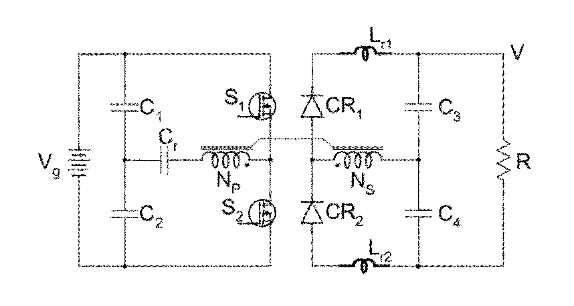
[0165]Several variants of the present invention are illustrated next. FIG. 36a illustrates a high voltage converter with 1:N step-up transformer and with both resonant capacitor and resonant inductor located on the transformer primary side. In some applications, one could design the isolation transformer so that its leakage inductance serves as the resonant inductor, thus eliminating the need for separate external resonant inductor as illustrated in FIG. 36b.

[0166]For low voltage application a N:1 step-down transformer as in FIG. 37a is preferred. In addition to reduce conduction losses of output switches, MOSFET synchronous rectifiers, as illustrated in FIG. 37a, replace the current rectifiers. The primary side switches could then be driven with a primary low-side / high-side driver, while the secondary side switches could be driven with another low-side / high-side driver referenced to secondary side as illustrated in FIG. 37b.

[0167]Finally, when the leakage inductance of the isolat...


PUM


Abstract

The isolated voltage step-down switching DC-DC converter has one magnetic component, the isolation transformer, and two small size resonant inductors. The transformer is built on a magnetic core with no air-gap, hence no DC storage and thus results in fast load transient response. Two active switches on the primary side have voltage stresses equal to input voltage and two current rectifiers on secondary side have voltage stresses equal to output DC voltage under all operating duty ratio conditions. The converter operates with two independent resonance's, one coinciding with the ON-time interval and the other coinciding with the OFF-time interval resulting in all switches being turned ON and turned OFF at zero current. Primary side high voltage switches operate with zero-voltage switching for all load currents. Despite the two resonance's, the output voltage is controlled by use of the variable duty ratio, constant switching frequency PWM method.

Description

CROSS-REFERENCE TO RELATED APPLICATIONS Field of Invention[0001]The general field of invention is switching PWM DC-DC converters and Resonant DC-DC converters with isolation and step-down DC voltage gain.[0002]The present invention uses also in a novel resonant way the capacitive energy storage and transfer first introduced in (1, 2). The classical, so called true resonant converters, are covered in detail in (3). The resonant conversion using resonant switches is investigated in (4). Finally, Quasi-Resonant switching converters are analyzed thoroughly in (5).[0003]The present invention opens up a new category of isolated DC-DC converter topology with only one magnetic component, the isolation transformer, and with no inductors. The isolation transformer does not store any DC energy at any operating duty ratio point as opposed to presently known isolated DC-DC converters which do store DC energy in either transformer or the inductors, or in both.[0004]The present invention also mark...

Claims


Application Information

Patent Timeline
IPC IPC(8): H02M3/335
CPCH02M3/335H02M3/337Y02B70/1491H02M2001/0058Y02B70/1433Y02B70/10H02M1/0058H02M3/33571H02M3/01
Inventor CUK, SLOBODAN
Owner CUK SLOBODAN
Why Eureka
Try Eureka