
User equipment, base station device, and communication control method

Active Publication Date: 2012-02-23
NTT DOCOMO INC
View PDF8 Cites 68 Cited by
  • Summary
  • Abstract
  • Description
  • Claims
  • Application Information

AI Technical Summary

Benefits of technology

[0032]As has been described above, according to the present invention, it is possible to provide a user equipment, a base station device, and a communication control method, which can reduce an interference amount to frequency bands of adjacent systems even when transmitting an uplink signal through a multicarrier using a plurality of transmission antennas or transmitters, or one transmission antenna or transmitter.

Problems solved by technology

However, since a transmitter radiating a radio wave radiates an unnecessary wave (hereinafter, referred to as adjacent channel interference) in an outer band of a frequency band of an own system, although a frequency band has been separated, mutual interference occurs among a plurality of adjacent systems.
Therefore, when a power level of the unnecessary wave is high, it has a significant adverse influence on adjacent systems.
Therefore, when considering the cost and size of the mobile station, it may be difficult to reduce the above-mentioned unnecessary wave or satisfy the regulations of the above-mentioned adjacent channel interference and spurious emission.
However, in the LTE-Advanced mobile communication system, when the mobile station has transmitted the uplink signal through the multicarrier using the plurality of transmission antennas or transmitters, a problem may occur in which an interference amount to frequency bands of adjacent systems is increased, as compared with the case in which the mobile station has transmitted the uplink signal through a single carrier using one transmission antenna or transmitter.
The problem also exists in the case in which the uplink signal is transmitted through a multicarrier using one transmission antenna or transmitter.

Method used


Image

  • User equipment, base station device, and communication control method
  • User equipment, base station device, and communication control method
  • User equipment, base station device, and communication control method

Examples


Embodiment Construction

Configuration of Mobile Communication System According to First Embodiment of the Present Invention

[0047]With reference to the accompanying drawings, a mobile communication system according to a first embodiment of the present invention will be explained. In all drawings for explaining the present embodiment, the same reference numerals are used to designate elements having the same function, and redundant description will not be repeated.

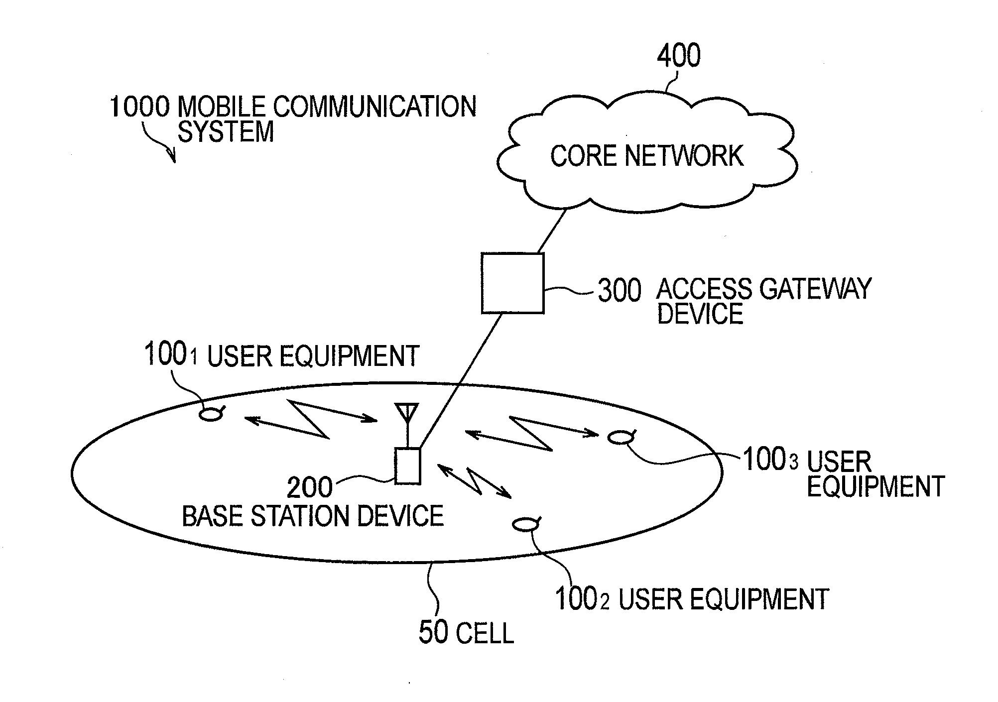
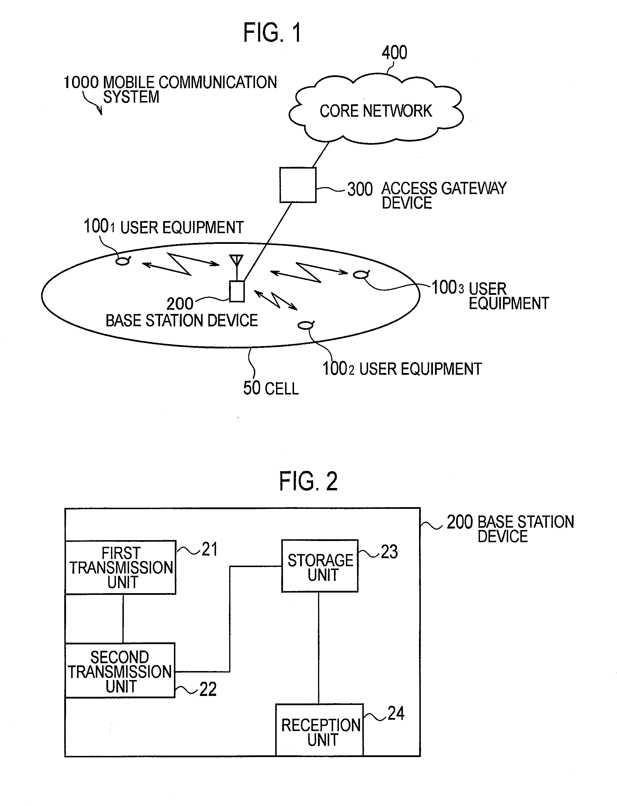
[0048]With reference to FIG. 1, a mobile communication system including a user equipment 100n and a base station device 200 according to the present embodiment will be explained.

[0049]A mobile communication system 1000, for example, is a system which employs an “Evolved UTRA and UTRAN (another name: Long Term Evolution or Super 3G)” scheme or an LTE-advanced scheme.

[0050]The mobile communication system 1000 includes the base station device (eNB: eNodeB) 200, a plurality of user equipments 100n (1001, 1002, 1003, . . . , 100n, n is an integer>0) whi...


PUM


Abstract

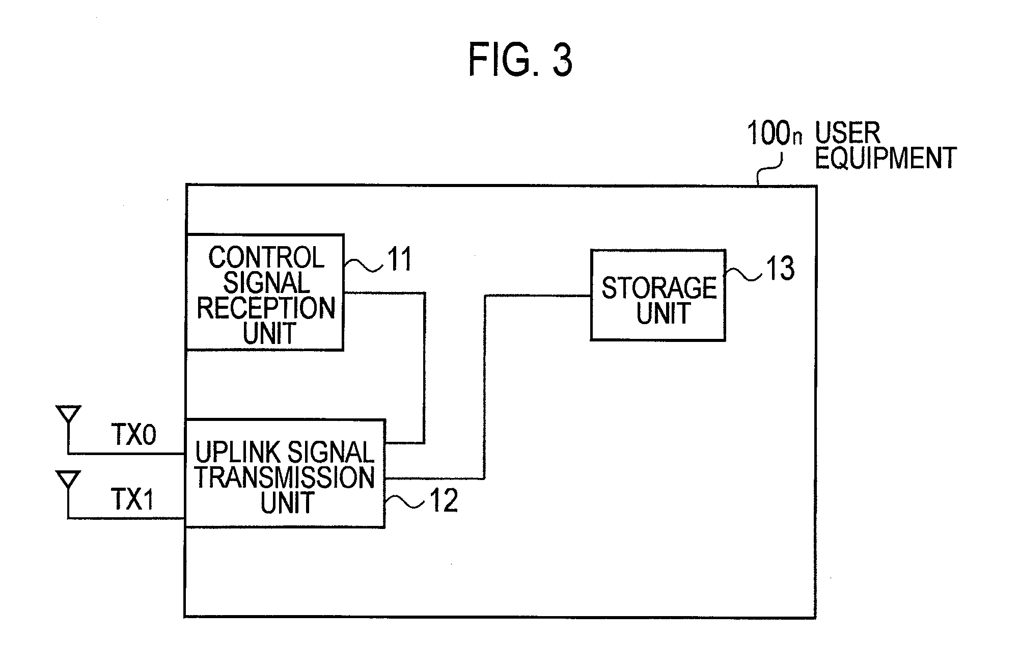
A radio base station including a user equipment configured to execute radio communication with a base station device in a mobile communication system. The user equipment includes a control signal reception unit configured to receive a control signal providing instructions to transmit an uplink signal and an uplink signal transmission unit configured to transmit the uplink signal to the base station device on a basis of the control signal, the uplink signal transmission unit is configured to set a maximum value of transmission power of the uplink signal to be smaller than rated power defined by the mobile communication system on a basis of at least one of a parameter notified by the control signal and a number of transmission antennas or transmitters used for transmission of an uplink signal.

Description

TECHNICAL FIELD[0001]The present invention relates to a mobile communication technology field, and particularly to a user equipment, a base station device, and a communication control method, in a mobile communication system using a next generation mobile communication technology.BACKGROUND ART[0002]A communication scheme, which is the next generation of a WCDMA (Wideband Code Division Multiplexing Access) scheme, an HSDPA (High-Speed Downlink Packet Access) scheme, an HSUPA (High-Speed Uplink Packet Access) scheme and the like, that is, an LTE (Long Term Evolution) scheme has been discussed in the 3GPP, which is a standardizing group of the WCDMA, and specifying work of the LTE scheme has been conducted.[0003]As a radio access scheme in the LTE scheme, an OFDMA (Orthogonal Frequency Division Multiplexing Access) scheme has been defined for a downlink, and an SC-FDMA (Single carrier Frequency Division Multiplexing Access) scheme has been defined for an uplink.[0004]The OFDMA scheme ...

Claims


Application Information

Patent Timeline
IPC IPC(8): H04W52/18H04W72/00
CPCH04W52/146H04W52/367H04W52/18H04W52/34H04W52/42H04W52/243
Inventor ISHII, HIROYUKI
Owner NTT DOCOMO INC
Learn More