Patient Breathing Modeling

a breathing modeling and patient technology, applied in the field of patient breathing modeling, can solve the problems of pet requiring prolonged exposure to radioactive imaging agents, cost and exposure, and not necessarily improving the accuracy of real-time data being displayed, and achieve the effect of accurate representation

Inactive Publication Date: 2012-02-23
TYCO HEALTHCARE GRP LP
View PDF10 Cites 0 Cited by
  • Summary
  • Abstract
  • Description
  • Claims
  • Application Information

AI Technical Summary

Problems solved by technology

One problem that arises while using these localization methods is that, in order to provide information that is useful to a physician, a display must be used that shows a representation of the tool superimposed on an image of the lungs.
However, this would require constant exposure to X-ray radiation by both the patient and the medical staff during while performing the dynamic registration.
Doing so does not necessarily improve the accuracy of the real-time data being displayed because at least one of the data sets is being distorted.
Moreover, PET requires prolonged exposure to radioactive imaging agents.
This idea certainly reduces costs and exposure to radiation, however it necessarily compromises image accuracy.
Finally, Vilsmeier does not address developing a dynamic model.
Because the model is completely simulated, it is useful for studying lung movement and the effects of tumor, but it would not have application during a procedure on an actual patient.

Method used


Image

  • Patient Breathing Modeling
  • Patient Breathing Modeling
  • Patient Breathing Modeling

Examples


example 1

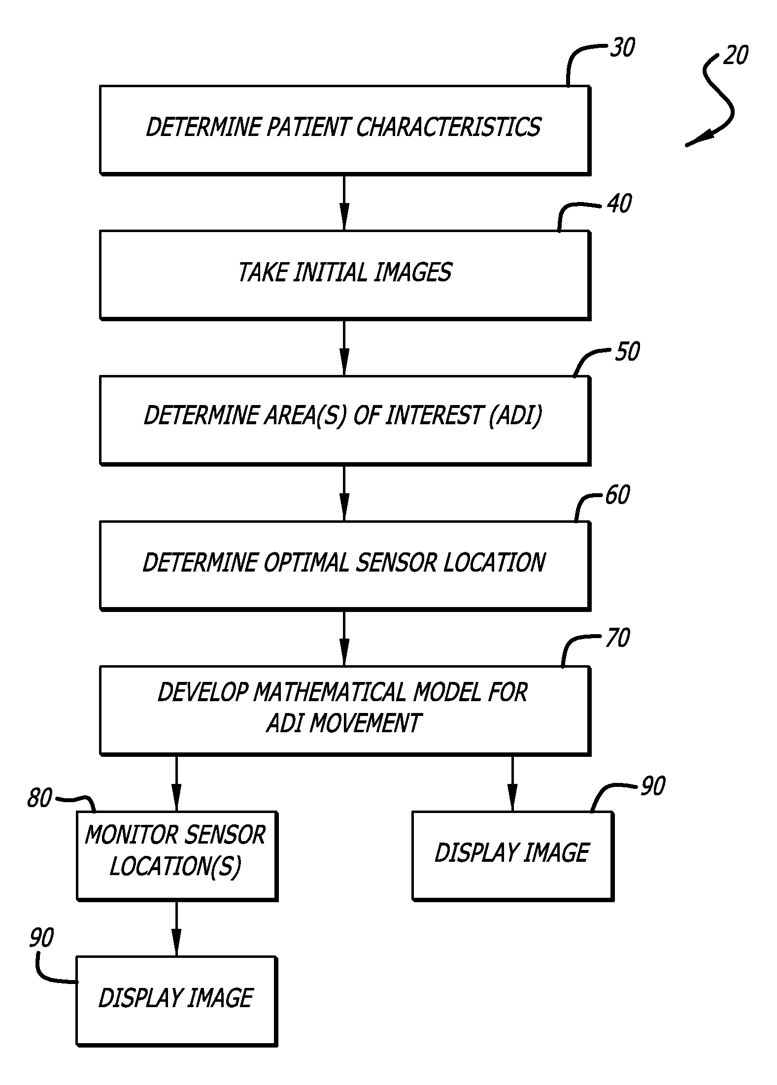
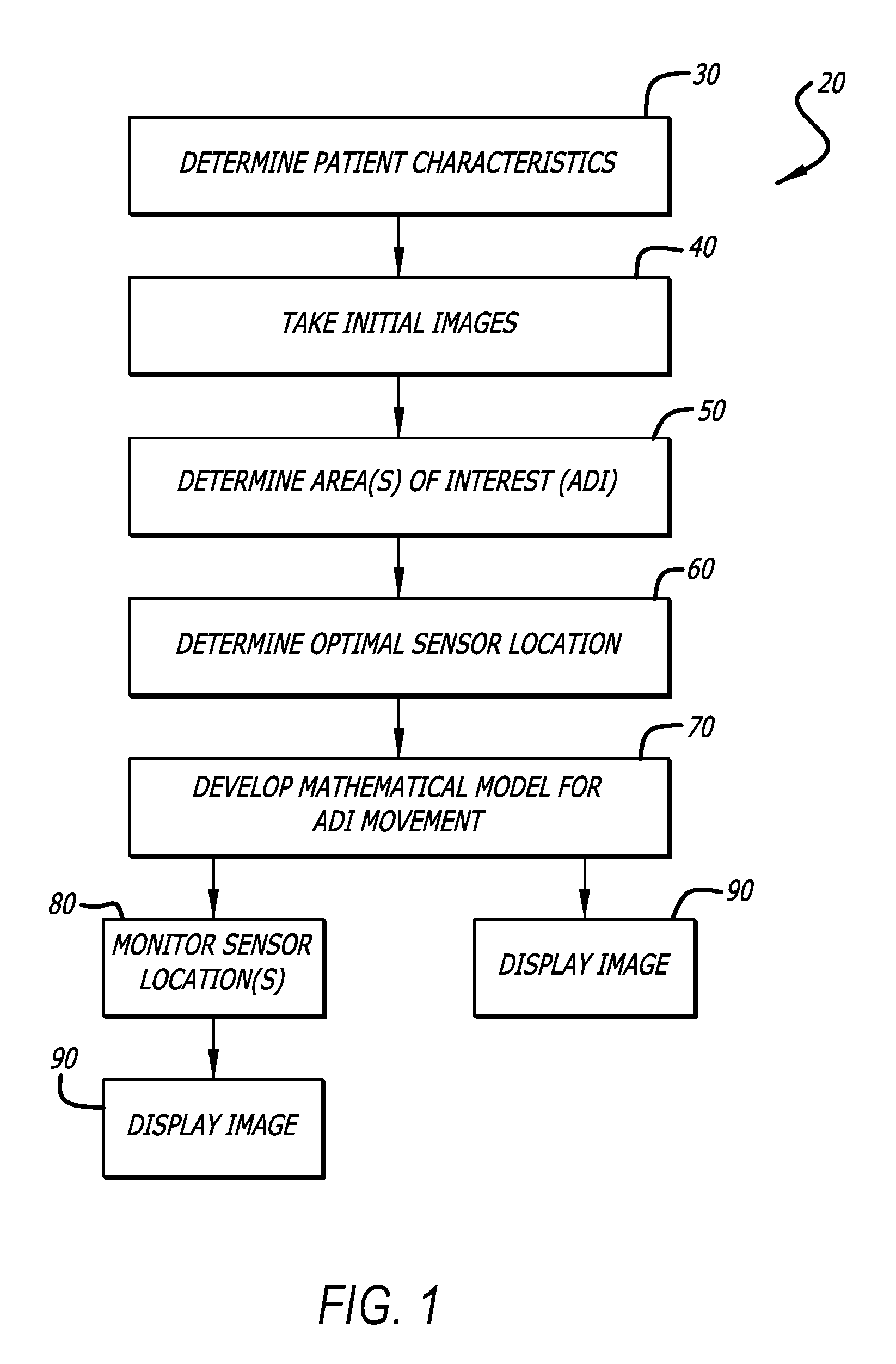
[0029]If multiple CT scans were acquired at 40, the data acquired at 80 may be used to determine which CT scan most accurately depicts the configuration of the lungs and can thus be superimposed onto the LG display.

example 2

[0030]The measured location of the LG can be corrected using the data acquired at 80. Rather than displaying the real-time data acquired by the LG system, which represents the position of the LG in relation to a magnetic field filling the AOI, the real-time data is manipulated so the LG appears in the correct location on the CT scan, which may be static or dynamic. In this way the tool may be localized more correctly inside the CT volume. The geometric model derived from the CT volume can thus be more accurately represented relative to the tool inside the body.

example 3

[0031]Using a well-known technique called image warping, the CT Volume can be changed dynamically using the data acquired at 80 and according to the monitored phase of breathing cycle. This can be used to display augmented images to perform the simulation of dynamic X-Ray modalities such as fluoroscopy, dynamic CT, etc., to simulate the patient physiology synchronized to the actual patient, study the tissue movement relative to the inserted tools, and for other purposes as well.

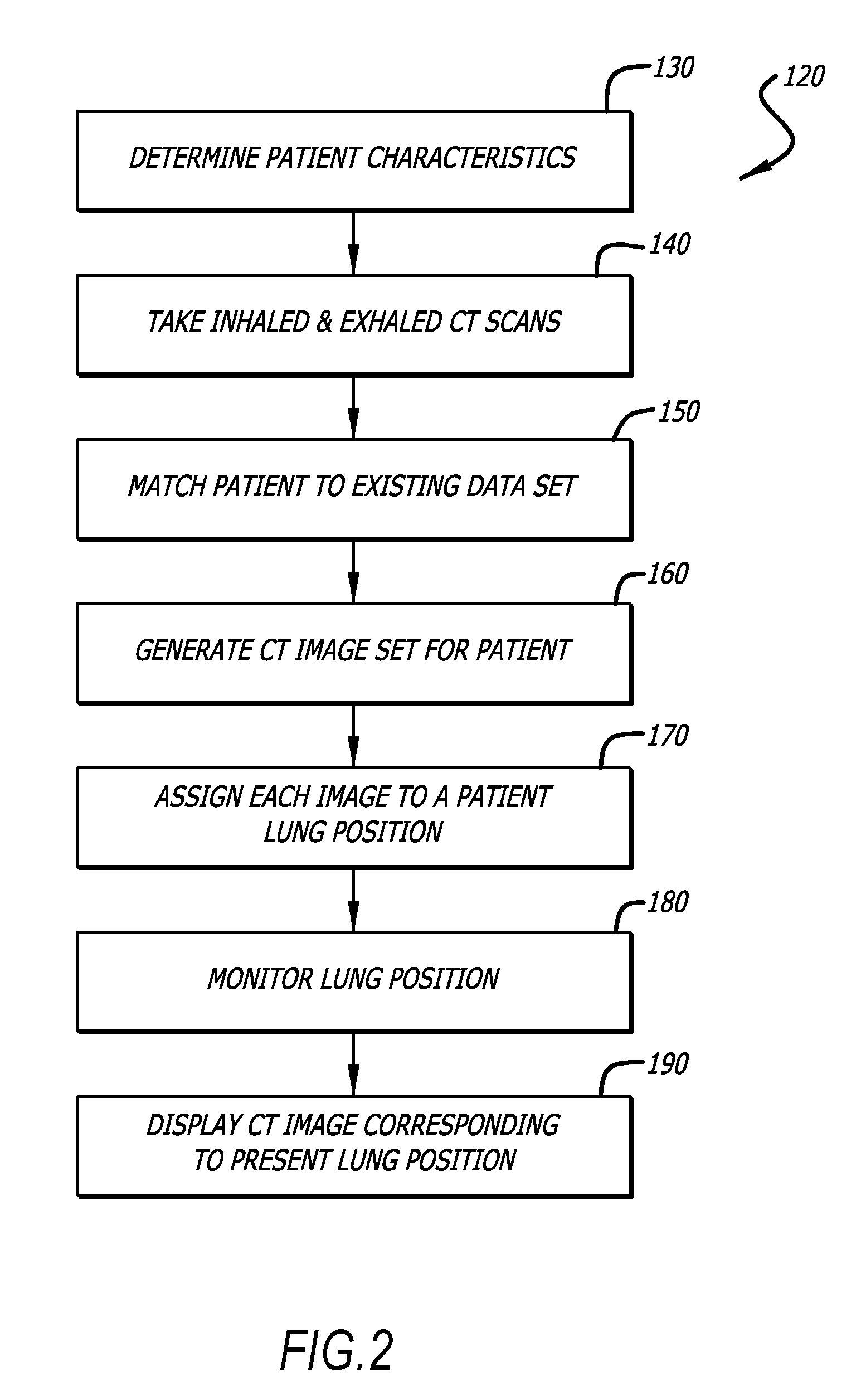
[0032]Referring now to FIG. 2, there is shown a flowchart that illustrates another embodiment 120 of the method of the present invention.

[0033]At 130 the patient characteristics are measured or determined. “Patient characteristics” is a term defined herein as any attribute of the patient that will influence the position of his or her lungs during any given point in the breathing cycle. Patient characteristics include, but are not limited to patient size (lung size), lung shape, lung health, altitude, patient ...


PUM


Abstract

A method of accounting for the movement of the lungs during an endoscopic procedure such that a previously acquired image may be dynamically registered with a display showing the position of a locatable guide. After an initial image set is acquired, an area of interest is identified and the movement thereof due to breathing is mathematically modeled. Patient movement sensors are then used to provide information on the patient's breathing patterns. This information is entered into the mathematical model in order to update the registration between the image set and a display showing the position of the locatable guide.

Description

RELATED APPLICATIONS[0001]This application claims priority to U.S. Provisional Application Ser. No. 60 / 948,640 filed Jul. 9, 2007 entitled Patient Breathing Modeling; and U.S. Provisional Application Ser. No. 61 / 043,987 filed Apr. 10, 2008 entitled Patient Breathing Modeling, all of which are hereby incorporated by reference.BACKGROUND OF THE INVENTION[0002]The method of the present invention relates generally to the accurate registration of a detected sensor located in moving lungs to a static image of the lungs. The evolution of procedures using less-invasive scopes has resulted in the development of sensors that can be attached to end of an endoscope and used to determine the three-dimensional location and orientation of the end of the endoscope. Examples of such sensor technology is shown and described in various patents and patent publications including U.S. Pat. No. 6,188,355 to Gilboa, U.S. Pat. No. 6,380,732 to Gilboa, U.S. Pat. No. 6,593,884 to Gilboa et al., U.S. Pat. No. ...

Claims


Application Information

Patent Timeline
Patent Type & Authority Applications(United States)
IPC IPC(8): A61B5/113
CPCA61B1/267A61B2019/505A61B6/541A61B5/06A61B5/066A61B2034/105
Inventor AVERBUCH, DORIAN
Owner TYCO HEALTHCARE GRP LP
Why Eureka
Try Eureka