Portable or wearable fracture treatment device
a treatment device and portable technology, applied in the field of portable or wearable fracture treatment devices, can solve the problems of patient's lifestyle restriction, treatment device placement, patient's considerable mental distress, etc., and achieve the effect of preventing muscular strength or visceral function impairment, facilitating the carrying of the treatment device, and reducing the size and weight of the entire devi
- Summary
- Abstract
- Description
- Claims
- Application Information
AI Technical Summary
Benefits of technology
Problems solved by technology
Method used
Image
Examples
first embodiment
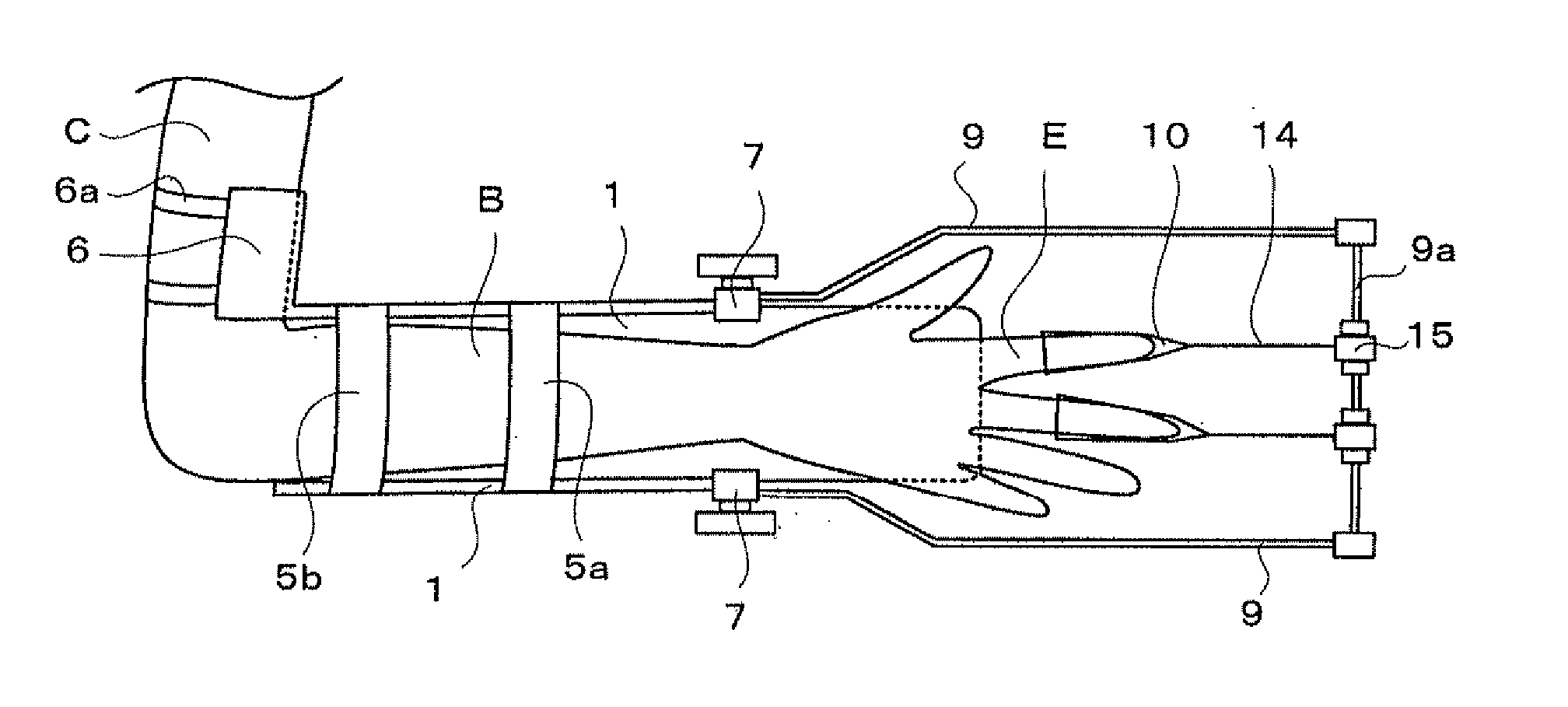
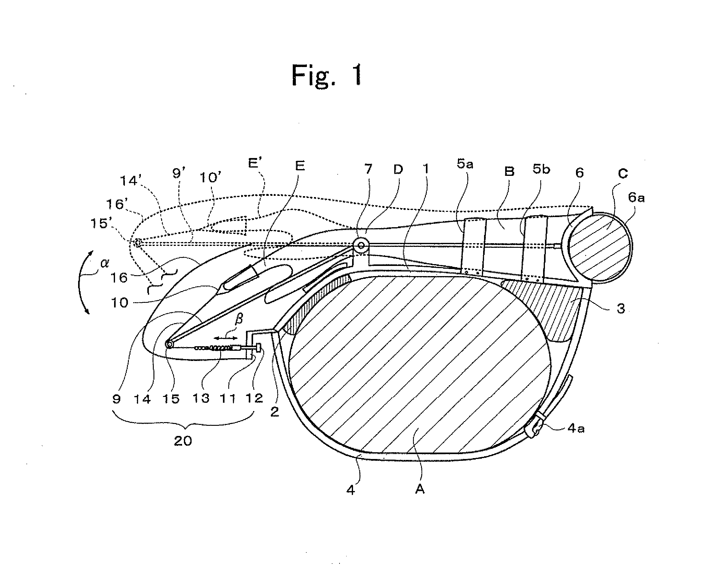
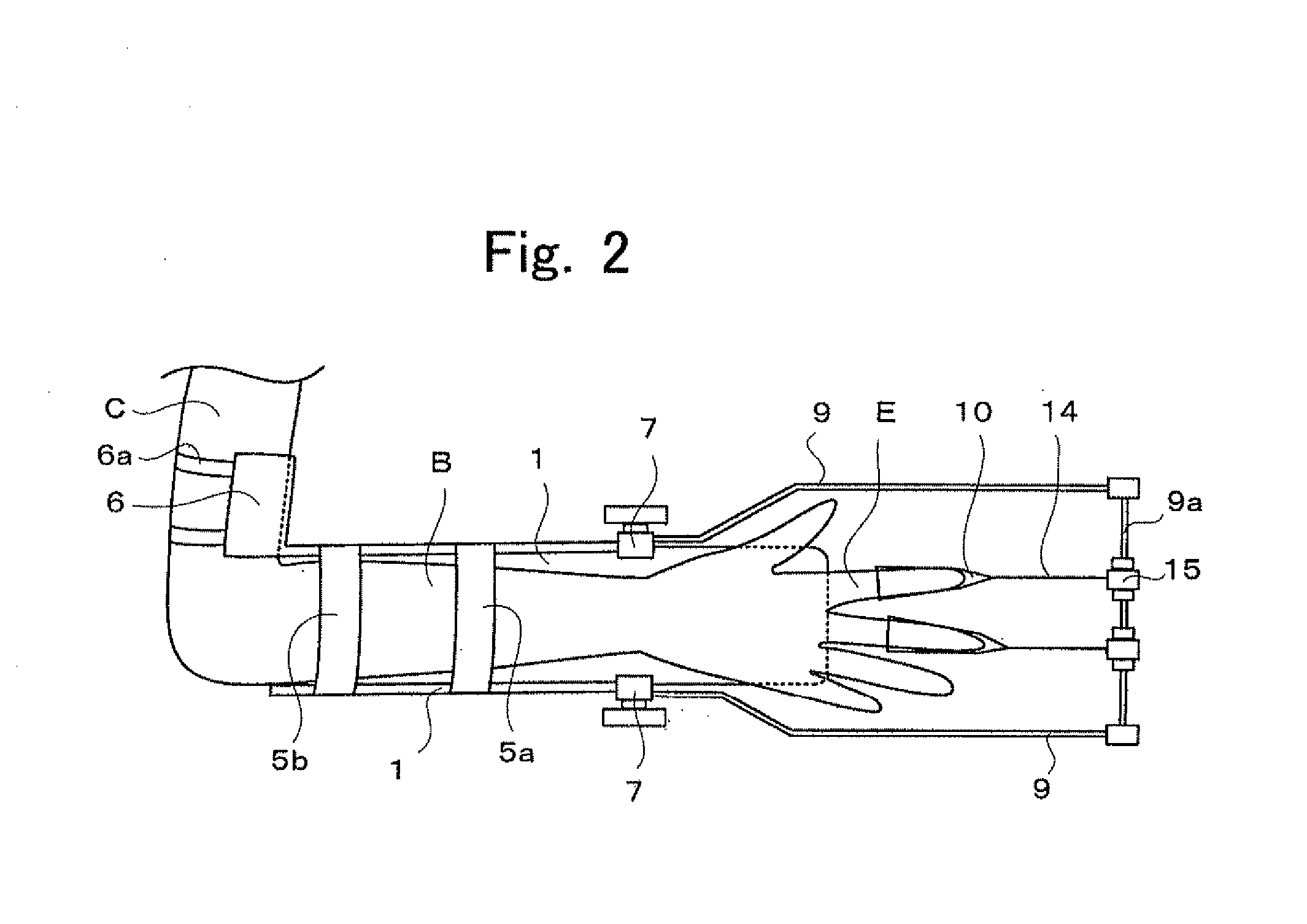
[0033]FIG. 1 illustrates a portable or wearable fracture treatment device according to the first embodiment of the present invention as seen from above a patient. FIG. 1 illustrates a trunk A of the patient, a forearm B of the patient, an upper arm C of the patient, a wrist D of the patient, and a finger E of the patient.
[0034]FIG. 1 illustrates a splint unit 1 (base unit), pads 2 and 3, a belt 4, and a buckle 4a of the belt 4. The splint unit 1 is made of a metal or a plastic. The splint unit 1 has a flat shape or a shape having a substantially U-shaped cross-section perpendicular to the longitudinal direction thereof (i.e., a shape that is curved so as to follow the surface of the forearm B of the patient). The pads 2 and 3 are made of a fabric or an elastic material such as a rubber and are fixed to the back surface of the splint unit 1 (which faces the trunk of the patient) with an adhesive or a hook-and-loop fastener (which is, for example, a hook-and-loop fastener marketed wit...
second embodiment
[0056]Referring to FIGS. 9A and 9B, a portable or wearable fracture treatment device according to a second embodiment of the present invention will be described. FIG. 9A illustrates the second embodiment attached to a forearm B of a patient as seen from above the forearm B, and FIG. 9B illustrates the second embodiment attached to the forearm B of the patient as seen from a side of the forearm B. In FIGS. 9A and 9B, components the same as those of FIG. 1 are denoted by the same numerals.
[0057]FIGS. 9A and 9B illustrate a proximal base unit 31, belts 32a and 32b, an upper arm contact unit 33, a fastener 33a (belt), a coil supporting unit 35, and an upper-arm-side coil fixing unit 36. The proximal base unit 31 has a shape having a substantially semicircular cross-section (a shape that is curved so as to follow the shape of the forearm B of the patient), and is fixed or attached to a part of the patient that is more proximal than the affected part (a part surrounding the forearm B or a...
PUM
 Abstract
Description
Claims
Application Information
 - R&D
- Intellectual Property
- Life Sciences
- Materials
- Tech Scout
- Unparalleled Data Quality
- Higher Quality Content
- 60% Fewer Hallucinations
Browse by: Latest US Patents, China's latest patents, Technical Efficacy Thesaurus, Application Domain, Technology Topic, Popular Technical Reports.
© 2025 PatSnap. All rights reserved.Legal|Privacy policy|Modern Slavery Act Transparency Statement|Sitemap|About US| Contact US: help@patsnap.com


