
Stent Graft Fenestration

Active Publication Date: 2012-02-23
BOSTON SCI MEDICAL DEVICE LTD
View PDF3 Cites 13 Cited by
  • Summary
  • Abstract
  • Description
  • Claims
  • Application Information

AI Technical Summary

Benefits of technology

[0016]Advantageously, the proposed method allows an intended user to relatively easily create the channel using an apparatus that has been advanced through a relatively tortuous path through the body of the patient, as minimal force is required be exerted onto the material with the distal end region of the apparatus in order to create the channel.
[0018]In addition, the proposed method is relatively safe for biological tissues adjacent to the foreign material, which minimizes risks of injuring these biological tissues and of creating potentially life-threatening situations.

Problems solved by technology

However, because of the configuration of the vessel, side branches extending from the vessel may be obstructed by the graft.
Restoration of flow through these side branches is relatively difficult to perform with a percutaneous needle because of the relatively large forces required.
Also, the relatively large forces exerted onto the needle create a risk that the needle will pass through the foreign material suddenly and damage adjacent tissues.

Method used


Image

  • Stent Graft Fenestration
  • Stent Graft Fenestration
  • Stent Graft Fenestration

Examples


example 1

[0100]In a first example, an embodiment of a proposed method is used to create a channel 512, seen in FIG. 5B, within a septal patch 510 made of foreign material, the septal patch 510 defining a material first surface 514 and a substantially opposed material second surface 516. The channel 512 extends between the material first and second surfaces 514 and 516. The septal patch 510 extends across an aperture 518 defined by the septum 520 of the heart 500 of the patient, for example an atrial septum or a ventricular septum. For example, the septal patch 510 covers the aperture and extends in a plane outside of the septum 520. In other examples, the septal patch 510 extends inside the aperture 518. Some of these procedures may involve patients that have had a septal defect repaired with the septal patch 510. In some cases, such patients may suffer from one or more conditions which require access to the left side of the heart for treatment to be performed. In such situations, access to ...

example 2

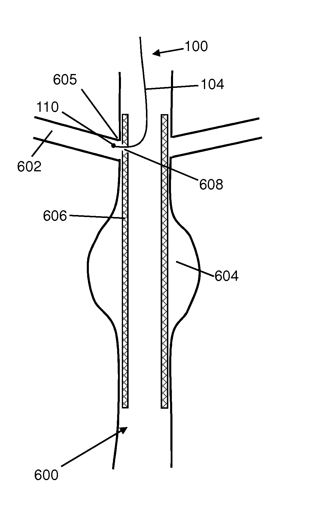
[0105]With reference first to FIGS. 6A and 6B, an antegrade approach to in-situ channel creation is provided. In this approach, the distal end region 104 is introduced into the body of the patient through the body vasculature inside the thoracic cavity, or in other words from a position superior to the diaphragm of the patient, and advanced towards the abdominal aorta 600 in which the electrode 110 is then positioned. FIG. 6A shows the electrode 110 of the apparatus 100 positioned in the abdominal aorta 600 substantially opposite the renal artery ostium 605, which is occluded by the stent-graft 606. At this point, energy may be delivered from an energy source through the electrode 110 in order to create a channel 608, as seen in FIG. 6B, in or through the stent-graft 606. FIG. 6B shows the electrode 110 after it has been advanced through the channel 608 into the renal artery 602. Creation of the channel allows for fluid communication and restoration of blood flow between the abdomin...

example 3

[0109]With reference now to FIGS. 8A-8D, alternate methods for in-situ creation of a channel through a stent-graft are illustrated. In the illustrated embodiments, a stent-graft 806, composed of a foreign material, has been placed to cover an aneurysm 804 in a section of the descending aorta, more specifically, within the thoracic aorta 800. As shown in these figures, the stent-graft 806 occludes the opening or ostium 805 of the Left Subclavian Artery (LSA) 802.

[0110]In the illustrated example, the positioning of the stent-graft 806 at the LSA ostium 805 is necessitated by the proximity of the LSA ostium 805 to the site of the aneurysm 804. A challenge is generally presented when an aneurysm 804 occurs within a vessel near an ostium of a side branch vessel, such as the LSA 802. It may become difficult to place the stent-graft 806 within the vessel to ensure protection of the aneurysm 804 while maintaining patency of the side branch ostium. In one such example, the aneurysm 804 and t...


PUM


Abstract

A method for creating a channel through a foreign material located in a body of a patient, the foreign material defining a material first surface and a substantially opposed material second surface, the channel extending through the foreign material between the material first and second surfaces, the method using an apparatus including an electrode, the method comprising: positioning the electrode substantially adjacent to the material first surface; energizing the electrode with a radiofrequency current; and using the electrode energized with the radiofrequency current to deliver energy into the foreign material to create the channel, wherein the foreign material is included in a stent graft.

Description

CROSS-REFERENCES TO RELATED APPLICATIONS[0001]This application is a continuation-in-part of U.S. patent application Ser. No. 11 / 905,448, filed on Oct. 1, 2007, which claims the benefit of U.S. provisional patent application Ser. No. 60 / 827,466 filed on 29th Sep. 2006. This application further claims the benefit of U.S. provisional application No. 61 / 448,578, filed on Mar. 2nd, 2011. All of these US patent applications and provisional patent applications are hereby incorporated by reference in their entirety.FIELD OF THE INVENTION[0002]The present invention relates generally to methods and devices usable to deliver energy within the body of a patient. More specifically, the present invention is concerned with a method for creating a channel through a stent graft.BACKGROUND OF THE INVENTION[0003]There are many situations in which it would be desirable to create a channel through a stent graft located in a body of a patient. For example, the following two papers give examples of such p...

Claims


Application Information

Patent Timeline
IPC IPC(8): A61B18/18
CPCA61B8/12A61B18/1492A61B2018/00083A61B2018/00214A61B18/04A61B2018/00827A61B2018/00875A61B2018/00898A61B2019/5466A61B2018/00702A61B2090/3966
Inventor BIADILLAH, YOUSSEFHARTLEY, AMANDADAVIES, GARETHVISRAM, NAHEEDJUZKIW, TARAS
Owner BOSTON SCI MEDICAL DEVICE LTD
Features
  • Generate Ideas
  • Intellectual Property
  • Life Sciences
  • Materials
  • Tech Scout
  • Unparalleled Data Quality
  • Higher Quality Content
  • 60% Fewer Hallucinations
Learn More