Adjustable Compression Staple and Method for Stapling with Adjustable Compression

a technology of adjustable compression and adjustable compression, which is applied in the field of adjustable compression staples and methods for stapling with adjustable compression, and can solve the problem of limited travel of the otc devi

Active Publication Date: 2012-02-23
CILAG GMBH INT
View PDF5 Cites 492 Cited by
  • Summary
  • Abstract
  • Description
  • Claims
  • Application Information

AI Technical Summary

Benefits of technology

[0015]When tissue is stapled, liquid is forced out of the tissue. The OTC range of the tissue is a compression range in which liquid is removed from the tissue (i.e., desiccates the tissue) without damaging or necrosing the tissue. As the liquid from the tissue exits the tissue due to compression exerted upon the tissue by the staple, however, the compressive force that is being imposed upon the tissue naturally reduces—because less mass is between the opposing staple portions. In some instances, this reduction can allow the imparted tissue compression to exit the OTC range. Staples according to the present invention each have a self-adjusting, pre-tensioned compression device that keeps compression force on the interposed tissue within the OTC compression range even after being desiccated.

Problems solved by technology

Travel of the OTC device can be limited, for example, by a star washer.

Method used


Image

  • Adjustable Compression Staple and Method for Stapling with Adjustable Compression
  • Adjustable Compression Staple and Method for Stapling with Adjustable Compression
  • Adjustable Compression Staple and Method for Stapling with Adjustable Compression

Examples


first embodiment

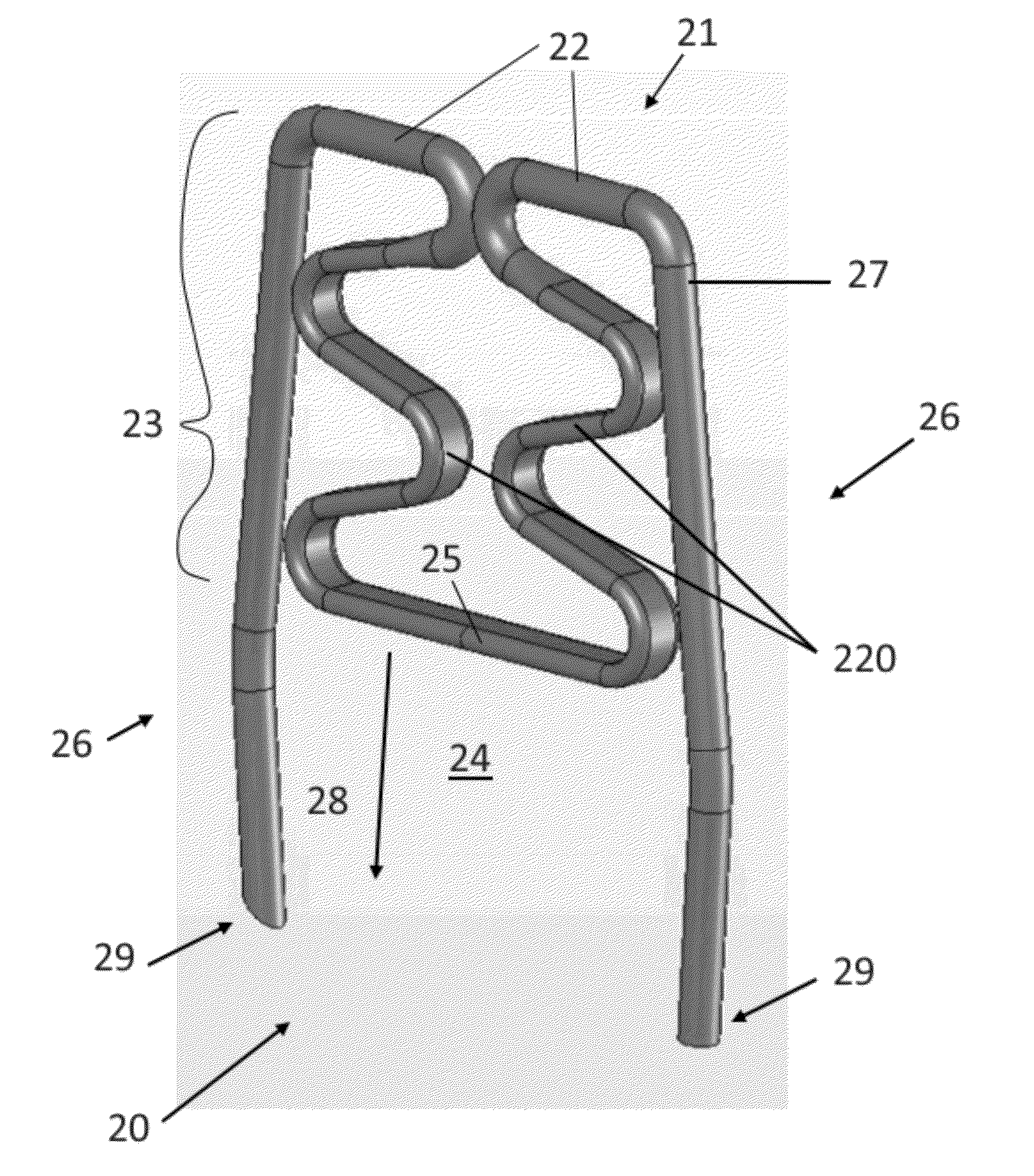
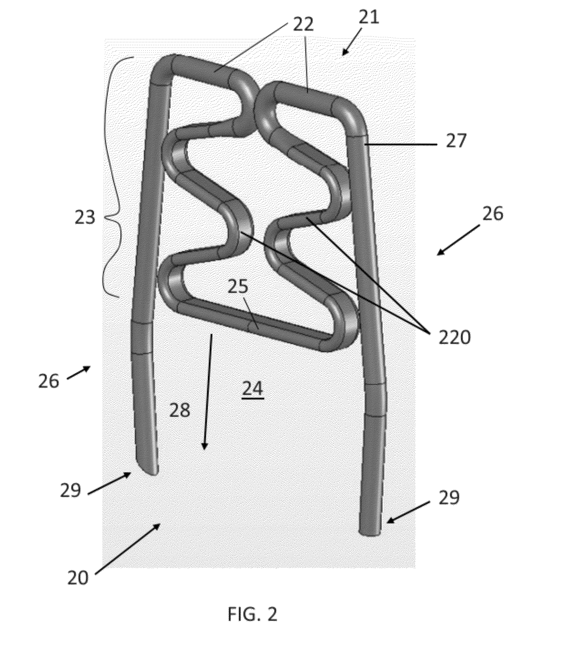
[0076]Referring now to the figures of the drawings in detail and first, particularly to FIG. 2 thereof, there is shown a first exemplary embodiment of an automatic optimal tissue compression (OTC) staple 20 according to the invention. In this first embodiment, the bridge 21 has an upper bridge portion 22 and an extension 23 that substantially increases the overall length of the bridge 21—as compared to the bridge 2 of the staple 1 of FIG. 1. As the upper bridge portion 22 transitions into the extension 23, it curves into and within the central region 24 of the staple 20. This extension 23 can be in any shape or of any material so long as it delivers a pre-set compressive force to the tissue at a compressing portion 25, and as long as it allows for absorption (within the area between the compressing portion 25 and the upper bridge portion 22) of forces greater than this pre-set force. Therefore, the shape can be trapezoidal, triangular, sinusoidal, or any other configuration. An exem...

second embodiment

[0081]In this second embodiment, the OTC device 33 behaves similar to the OTC portions of the embodiment of FIG. 2 and can be shaped with the same variations of cross-section and other spatial characteristics and can be formed with the same variations in material composition. Variation of any attribute of the OTC device 33 allows for adjustment of the compressive and reactive force constants thereof on the compressed tissue. The extension 36 can be any shape or material so long as it delivers a pre-set compressive force to the tissue at the compressing portion 34 and as long as it allows for absorption of forces greater than this pre-set force. An exemplary embodiment selected for this exemplary OTC device 33 is a relatively sinusoidal set of curves traversing less than two periods. The extension 36 has two mirror-symmetrical portions each starting from the bridge 31 and ending at respective ends of the compressing portion 34. In this exemplary embodiment, neither the extension 36 n...

third embodiment

[0083]Notably different from the embodiments of FIGS. 2 and 3 is the compressing portion 44. Here, the width of the compressing portion 44 (defined along the line between the two legs 42 of the staple 40) is greater than the separation distance of the two legs 42. The compressing portion 44 is provided with orifices 49 having a shape substantially corresponding to the cross-sectional shape of the upper portion of the staple legs 42 but slightly larger. The legs 42 pass through and slidably rest within these orifices 49. In such a configuration, movement of the OTC device 43 out of the bridge-legs plane is substantially prevented. Because the orifices 49 are shaped to be slightly larger than the cross-section of the legs 42, the extension 46 acts as a compression spring in the bridge-legs plane as the compressing portion 44 moves up and down along the upper portion of the legs 42 (up being defined as the direction towards the bridge 41 from the piercing tips of the legs 42). Thus, th...


PUM


Abstract

A method for applying and maintaining optimal tissue compression with a staple includes piercing tissue with deformable distal ends of staple legs, each distal end defining a stapling point shaped to pierce material, the two staple legs coupled to each other at base ends thereof by a bridge and together forming a substantially U-shaped staple body. The two staple legs enter the tissue until the tissue applies a compressive force to a compression device disposed at least partly between the two staple legs. The compression device has a compression surface movably disposed between the two staple legs and a compression resistor that is connected to the bridge and to the compression surface and operable to resist movement of the compression surface towards the bridge with a force. The two staple legs are deformed to maintain the compressive force between the tissue and the compression device.

Description

CROSS-REFERENCE TO RELATED APPLICATIONS[0001]This application is a divisional of U.S. patent application Ser. No. 11 / 971,998, filed on Jan. 10, 2008, which application claims the priority, under 35 U.S.C. §119, to U.S. Provisional Application Ser. No. 60 / 880,146, filed on Jan. 12, 2007, the entire disclosures of which are hereby incorporated herein by reference herein in their entireties.STATEMENT REGARDING FEDERALLY SPONSORED RESEARCH OR DEVELOPMENT[0002]n / aFIELD OF THE INVENTION[0003]The present invention lies in the field of staple fastening, in particular, staples and instruments capable of applying a single or a plurality of staples to a material and processes therefor. More particularly, the present invention relates to a staple capable of placing a load-bearing force against the material being stapled and improvements in processes for stapling material. The device can be used, particularly, in the medical field for stapling tissue during surgical procedures, whether open, end...

Claims


Application Information

Patent Timeline
Patent Type & Authority Applications(United States)
IPC IPC(8): A61B17/064
CPCA61B17/064F16B15/0015A61B17/0644A61B2017/0645
Inventor SMITH, KEVIN W.PALMER, MATTHEW A.KLINE, KOREYDEVILLE, DEREK DEE
Owner CILAG GMBH INT
Why Eureka
Try Eureka