
Compression device and control system for applying pressure to a limb of a living being

a technology of a control system and a compression device, which is applied in the field of compression devices, can solve the problems of affecting the function of the limb, so as to achieve the effect of less work

Active Publication Date: 2010-06-03
PARASOL MEDICAL
View PDF36 Cites 83 Cited by
  • Summary
  • Abstract
  • Description
  • Claims
  • Application Information

AI Technical Summary

Benefits of technology

[0018]More specifically, described herein is a compression device comprising a user interface, a programmable logic controller in electronic connection with the user interface, a battery power source in electronic connection with the programmable logic controller, a source of fluidic pressure in electronic connection with the battery power source and the programmable logic controller, a first valve having at first port in fluidic connection with the source of fluidic pressure and a second port in fluidic connection with a first inflatable bladder, a second valve having a first port in fluidic connection with the source of fluidic pressure and a second port in fluidic connection with a second inflatable bladder. The programmable logic controller is programmed to cause a repeating sequence of inflating the first inflatable bladder by opening the first and second ports of the first valve, closing the first and second ports of the second valve, and activating the source of fluidic pressure, then after a first period of time, deflating the first inflatable bladder by deactivating the source of fluidic pressure, inflating the second inflatable bladder by closing the first and second ports of the first valve, opening the first and second ports of the second valve, and activating the source of fluidic pressure, waiting for a second period of time, then deflating the second inflatable bladder by deactivating the source of fluidic pressure. The user interface allows the user to select a mode that extends the life of the battery power source by selecting the first period of time and the second period of time such that the life of the battery will last for a desired time.
[0019]In addition, described herein is a compression device comprising a user interface, a programmable logic controller in electronic connection with the user interface, a power source in electronic connection with the programmable logic controller, a source of fluidic pressure in electronic connection with the power source (if the electronic connection is needed) and the programmable logic controller, a first valve having at first port in fluidic connection with the source of fluidic pressure, a second port in fluidic connection with a first inflatable bladder, and a third port in fluidic connection with a second valve. The second valve has a first port in fluidic connection with the source of fluidic pressure, a second port in fluidic connection with a second inflatable bladder, and a third port in fluidic connection with the first valve. The programmable logic controller is programmed to cause the repeating sequence of: (a) inflating the first inflatable bladder by opening the first and second ports of the first valve, closing the third port of the first valve, closing the first and second ports of the second valve, and activating the source of fluidic pressure; (b) after a first period of time, deflating the first inflatable bladder and partially inflating the second inflatable bladder by deactivating the source of fluidic pressure, closing the first port of the first valve, opening the third port of the first valve, opening the third port of the second valve, and opening the second port of the second valve; (c) further inflating the second inflatable bladder by closing the first, second, and third ports of the first valve, opening the first and second ports of the second valve, closing the third port of the second valve, and activating the source of fluidic pressure; and (d) after a second period of time, deflating the second inflatable bladder and partially inflating the first inflatable bladder by deactivating the source of fluidic pressure, closing the first port on the second valve, opening the third port of the second valve, opening the third port of the first valve, and opening the second port of the first valve. In this manner, the fluid pressure within the first inflatable bladder, when allowed to deflate, partially inflates the second inflatable bladder (and vice-versa), thus requiring less work by the source of fluidic pressure and the power source.
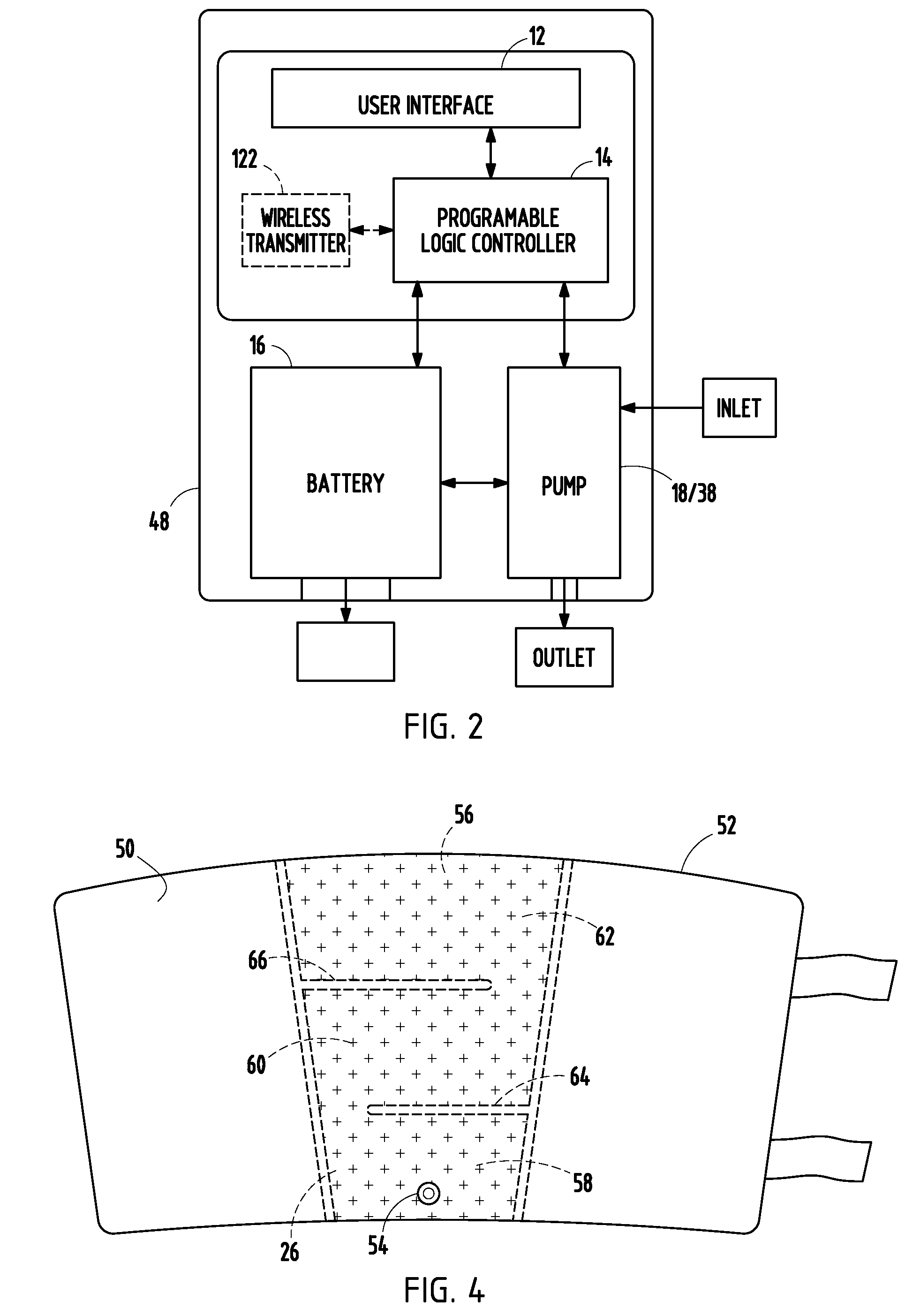
[0023]In addition, described herein is a method of compressing a body part comprising the steps of: (a) presenting a compression device; (b) at least partially surrounding a body part of a living being with the compression device; and (c) using the source of fluidic pressure to inflate the inflatable bladder. The compression device comprises an inflatable bladder. The inflatable bladder comprises an inlet port and an interior volume, the inlet port being in fluidic communication with the interior volume and a source of fluidic pressure. The interior volume comprises a first chamber, a second chamber, and a third chamber, the first chamber in fluidic communication with the second chamber, and the second chamber in fluidic communication with the third chamber. A first divider partially separates the first chamber from the second chamber. A second divider partially separates the second chamber from the third chamber. This method can also be used to treat or prevent a chronic wound by enhancing circulation (in addition to the other purposes described above).
[0025]In addition, described herein is a method of compressing a body part comprising the steps of: (a) presenting a compression device; (b) at least partially surrounding a body part of a living being with the compression device; and (c) using the source of fluidic pressure to inflate the inflatable bladder. The compression device comprises an inflatable bladder. The inflatable bladder comprises an inlet port in fluidic communication with a source of fluidic pressure. The inflatable bladder further comprises a first chamber, a second chamber, a third chamber, a first check valve, and a second check valve. The first chamber is in fluidic communication with the inlet port and the second chamber, through a first check valve. The second chamber is in fluidic communication with the third chamber, through a second check valve. The first check valve and the second check valve are capable of causing the first chamber to inflate fully before the second chamber inflates fully, and the second chamber to inflate fully before the third chamber inflates fully. This method can also be used to treat or prevent a chronic wound by enhancing circulation (in addition to the other purposes described above).
[0028]In addition, herein described is a method of treating a wound comprising the steps of: (i) presenting a body part of a living being, the body part having a wound and an area adjacent to the wound; (ii) presenting a compression device comprising an inflatable bladder in fluid communication with a source of fluidic pressure; (iii) at least partially surrounding the area of the body part adjacent to the wound with the compression device; and (iv) using the source of fluidic pressure to inflate the inflatable bladder to increase circulation in the body part.

Problems solved by technology

Deep Vein Thrombosis is a blood clot that can form in a person's legs and sometimes move to his or her lungs, where it could potentially be fatal.
The inventive compression device may be used in DVT prevention, although a user should consult a physical before doing so, as any compression device could release a dangerous blood clot.
Lymphedema causes the extremity to swell and become heavy and limited in mobility and function.
Chronic venous insufficiency occurs when these valves become damaged, allowing the blood to leak backward and pool.
CVI is a significant public health problem in the United States.
CVI can lead to leg ulcers which can be severe and are responsible for 100,000 cases of disability in the United States alone.
Left untreated, varicose veins may worsen over time.
Large varicose veins can cause aching and feelings of fatigue as well as skin changes like rashes, redness, and sores.
When the arteries in the legs become blocked, the legs do not receive enough blood or oxygen.
With four tubes running to each compression sleeve, there is an increased likelihood of getting the tubes tangled or pinched.

Method used


Image

  • Compression device and control system for applying pressure to a limb of a living being
  • Compression device and control system for applying pressure to a limb of a living being
  • Compression device and control system for applying pressure to a limb of a living being

Examples


first embodiment

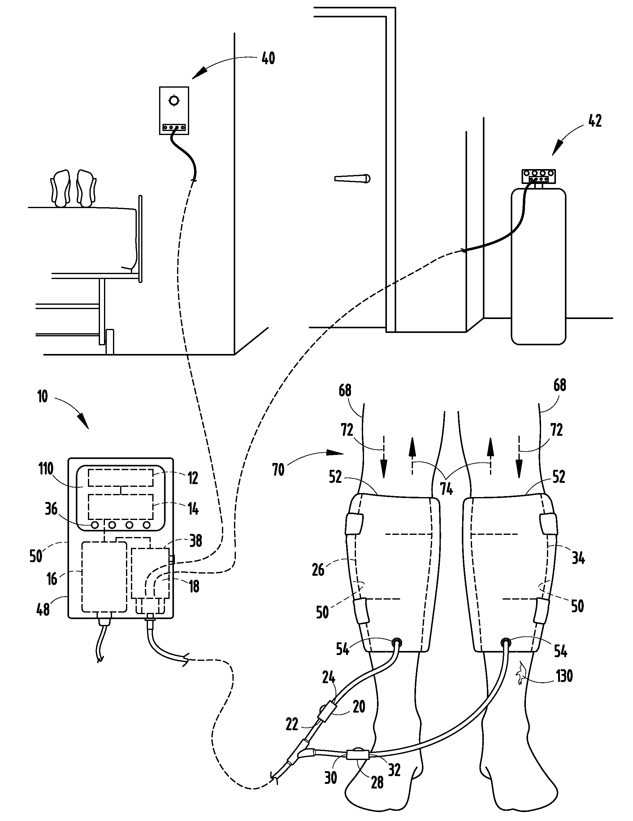
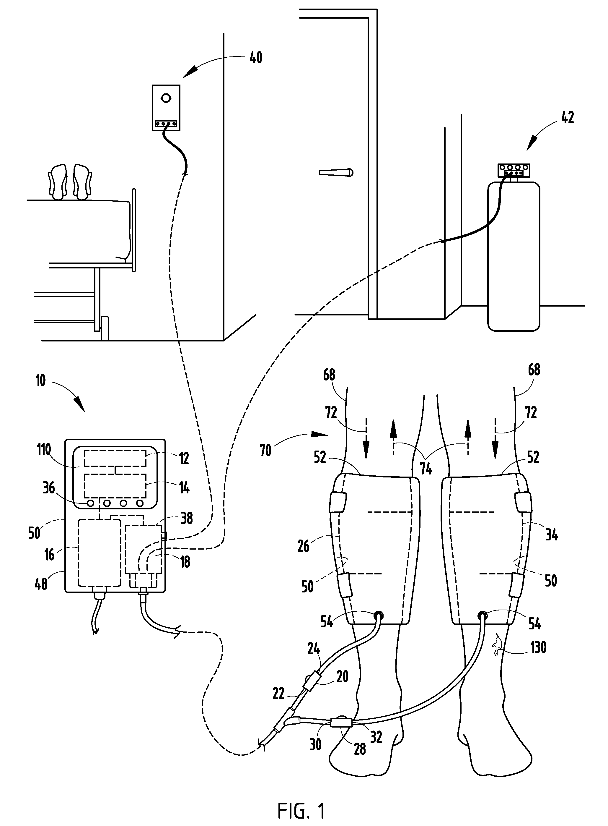
[0036]In a first embodiment, compression device 10 (FIG. 1) generally comprises a housing 48 for a user interface 12, a programmable logic controller 14, access to a power source 16 (such as a battery), and access to a source of fluidic pressure 18. The user interface 12 can provide a data display 110 to inform the user of important data such as battery life, pressure settings, and timing intervals. The user interface 12 can have buttons or a pressure sensitive screen to allow the user to select various operating modes, set variables, such as pressures, timing intervals, and the order in which specific inflatable bladders (discussed below) will be inflated and / or deflated. The user interface 12 is in electronic connection with the programmable logic controller 14 and the power source 16. For example, the user interface 12 can have a button or pressure sensitive touch option that, when pressed, communicates with the programmable logic controller 14. As a consequence, the user interfa...

second embodiment

[0042]In a second embodiment, the compression device 10 comprises a user interface 12 (FIG. 1), a programmable logic controller 14, a power source 16, and a source of fluidic pressure 18. The programmable logic controller14 is in electronic connection with the user interface 12. The power source 16 is in electronic connection with the programmable logic controller 14. The power source 16 can be a battery. The source of fluidic pressure 18 is in electronic connection with the power source 16 (if needed to activate the source of fluidic pressure 18) and the programmable logic controller 14.

[0043]This embodiment of the compression device 10 further comprises a first valve 20 (FIG. 3), a first inflatable bladder 26, and a second valve 28. The first valve 20 has a first port 22 in fluidic connection with the source of fluidic pressure 18, a second port 24 in fluidic connection with the first inflatable bladder 26, and a third port 44 in fluidic connection with the second valve 28. The se...


PUM


Abstract

A device to compress the limb of a living being comprising a user interface, a programmable logic controller, a power source, a source of fluidic pressure, valves with ports in fluidic connection with the source of fluidic pressure, other valves, and a first and second inflatable bladders, wherein the programmable logic controller is programmed to cause the repeating sequence of inflating the first inflatable bladder by manipulating the ports of the valves, after a first preset period of time, deflating the first inflatable bladder and allowing the pressure within the first inflatable bladder to inflate partially the second inflatable bladder by manipulating the ports of the valves. The source of fluidic pressure can be a self-contained pump, a connection to fluidic pressure in a health care facility, or a pressurized canister. The power source can be a battery. The device has means to extend the life of the power source.

Description

CROSS-REFERENCE TO RELATED APPLICATIONS[0001]This application claims the benefit of U.S. Provisional Application No. 61 / 221,650, filed Jun. 30, 2009, and U.S. Provisional Application No. 61 / 119,235, filed Dec. 2, 2008. Both said provisional applications are incorporated herein in their entireties.BACKGROUND[0002]The present invention generally relates to a compression device for treating various circulatory disorders and generally improving circulation for users such as athletes, people with wounds, and people who have to sit for a long period of time. More specifically the present invention relates to a compression device with inflatable bladders and a control system for applying compressive pressure to a body part of a living being.[0003]The inventive compression device may be used to treat any or all of the following circulatory disorders: deep vein thrombosis (DVT), lymphedema, chronic venous insufficiency (CVI), varicose veins, and peripheral arterial disease (PAD).[0004]Deep V...

Claims


Application Information

Patent Timeline
Patent Type & Authority Applications(United States)
IPC IPC(8): A61H7/00A61B17/00
CPCA61B17/1355A61H9/0078A61H1/008A61H2201/5046A61H2205/106A61H2201/165
Inventor EDDY, PATRICK
Owner PARASOL MEDICAL
Learn More