Compression device for the foot

a compression device and foot technology, applied in the field of compression devices for the foot, can solve the problems of reducing the residence time of blood supplied to the lower limb, tissue breakdown, and known devices not only affect patient mobility, but also are aesthetically unacceptable to many patients, and achieve the effect of not reducing mobility

Active Publication Date: 2007-02-15
SWELLING SOLUTIONS
View PDF87 Cites 70 Cited by
  • Summary
  • Abstract
  • Description
  • Claims
  • Application Information

AI Technical Summary

Benefits of technology

[0013] We have found that such a device may bring the advantages of applying pressure to the heel and arch of the patient without reducing mobility. The pressure can also be targeted on the area of the heel where ulcers are most prevalent. Independent supply and control of fluid to two bladders means that the device can be operated in a number of ways. This flexibility enables a range of treatments to be provided by the device and, thus, allows one device to treat a number of different indications.

Problems solved by technology

This in turn reduces the residence time for blood supplied to the lower limb and the severity of ischaemic episodes within the limb that can result in tissue breakdown.
The known devices apply pressure to the foot and to the rest of the limb through a thick cuff which is large, bulky and powered mainly by electricity.
The known devices not only affect patient mobility but are also aesthetically unacceptable to many patients.
In the hospital devices, these disadvantages are not apparent because the patient is largely confined to bed.
A problem in providing an aesthetically acceptable foot cuff is one of supplying the pneumatic fluid to the cuff.
If a tube is used to supply the fluid to, for instance, the arch of the foot, the shoe may collapse or kink the tube and may cause pressure points on the foot.
In addition, a problem with the devices of the prior art is that the cuff is generally cylindrical and applies pressure over the whole of its surface to the foot, meaning that the mobility of the ankle is reduced making walking difficult even if the patient can wear a shoe and inflate the cuff.
The effect of radius is a fundamental limitation of elasticated bandages and stockings.
In addition, it is difficult to apply pressure to the heel of the foot with an elastic bandage and this is an area in which ulcers occur.
This reduction in mobility impairs venous return as the patient is unable to walk normally.

Method used


Image

  • Compression device for the foot
  • Compression device for the foot
  • Compression device for the foot

Examples


second embodiment

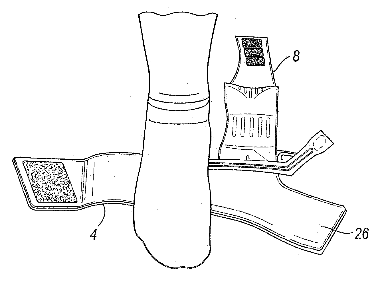
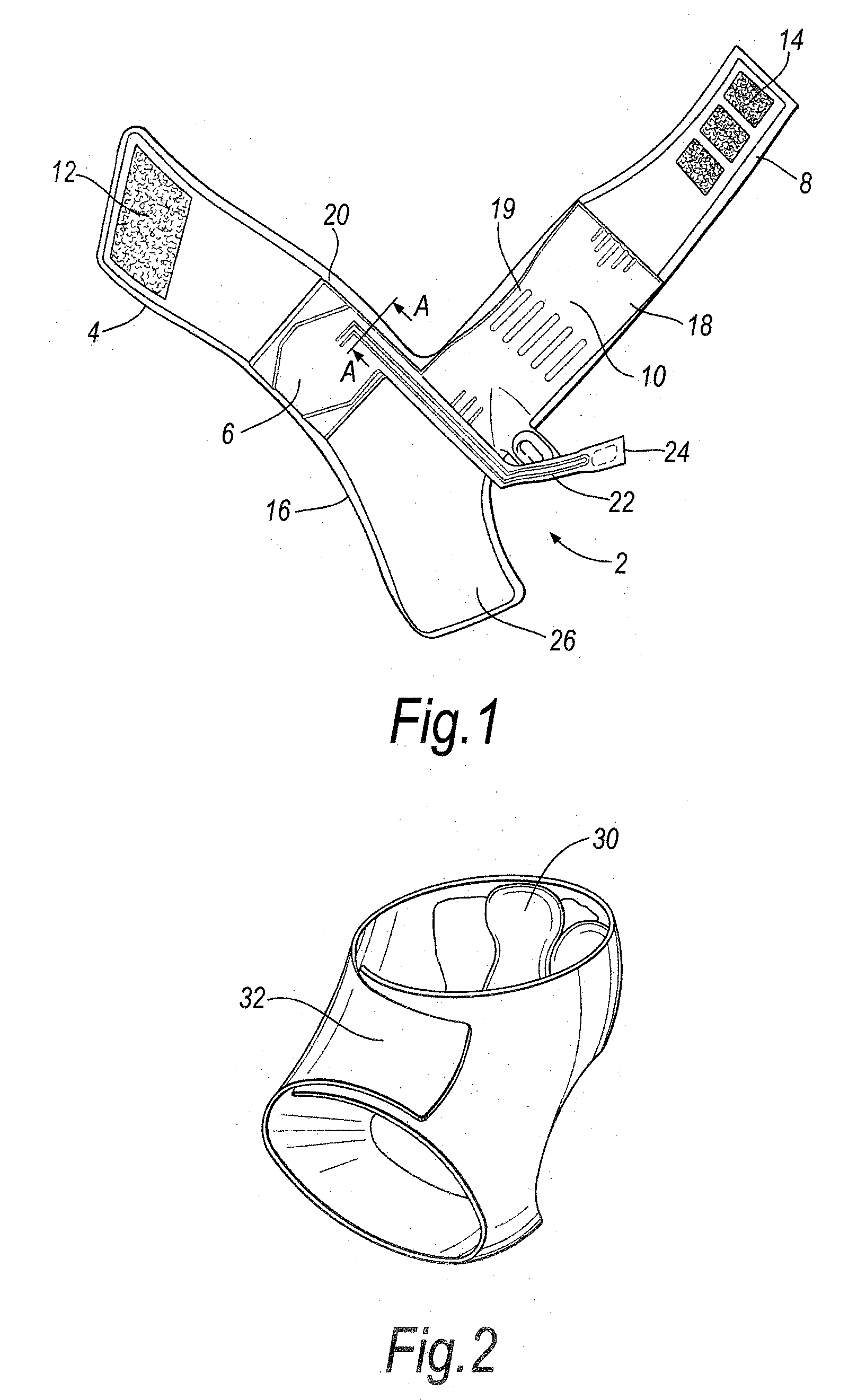
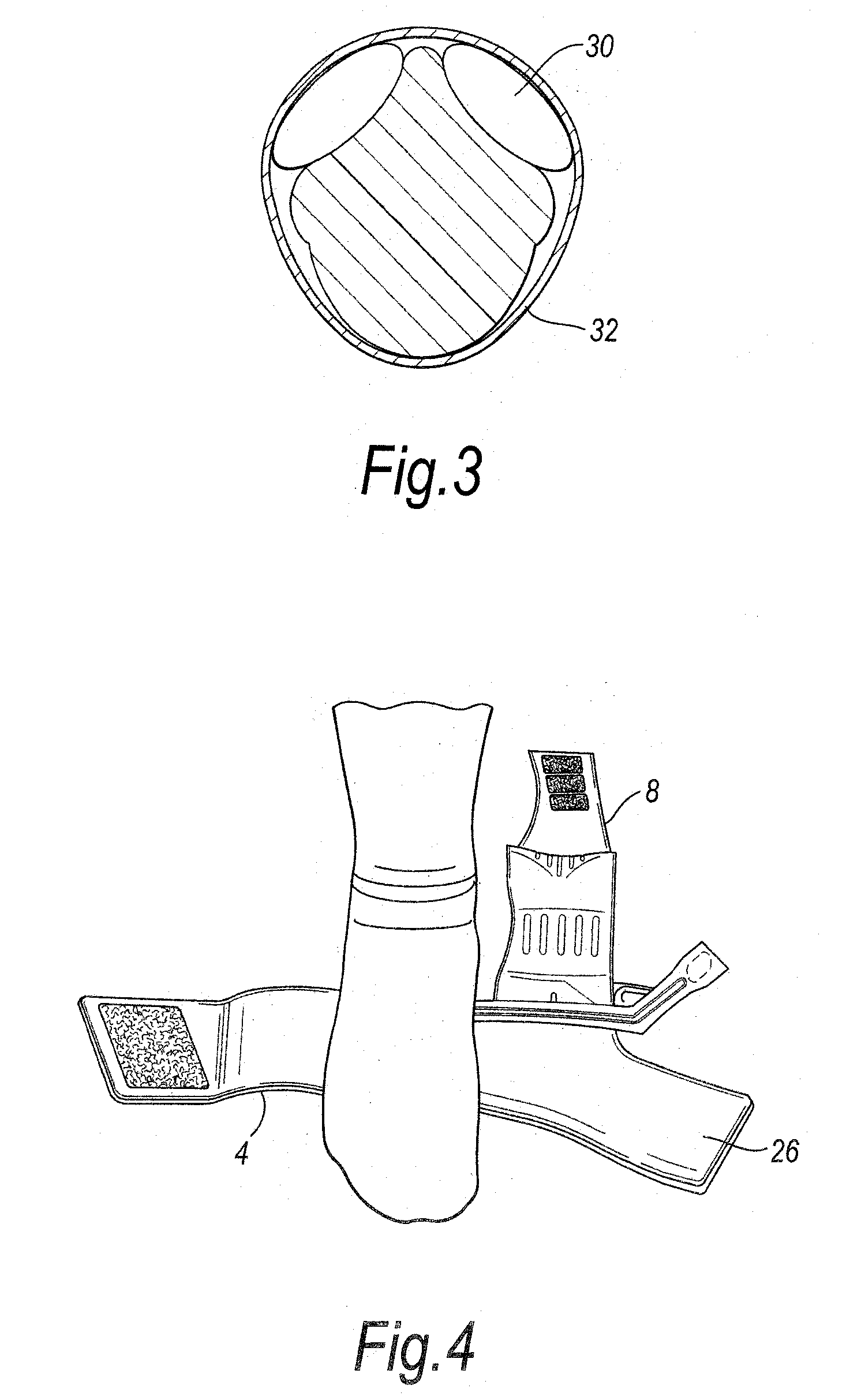
[0036] In a second embodiment, the invention provides a cuff for providing compression to a limb, the cuff comprising an outer wall joined to an inner wall to form a bladder, the bladder being provided with a spacer to separate the walls to create a channel for fluid to flow into and out of the bladder.

[0037] The advantage of the cuff of the invention is that the separating means allow the bladders to be shaped so that the compression generated by the device can be focused on those areas where ulcers are more prevalent without compromising the path for fluid movement.

[0038] The spacer is made from a relatively incompressible material that spaces the walls apart but does not allow the bladder or channel to become obstructed in the manner that a tube may become obstructed by kinking or collapsing or being flattened against, for instance, a shoe.

[0039] Preferably, the bladder walls are selectively welded together so that inflation of the bladder is limited in the welded areas which c...

third embodiment

[0042] In a third embodiment, the invention provides a channel for connecting one or more bladders to each other or to a controller, the channel comprising an elongate outer wall joined to an elongate inner wall, the channel being provided with means to separate the walls to create a path for fluid to flow into and out of the channel.

[0043] The separating means are preferably a spacer provided on at least one wall of the channel and even more preferably a spacer provided on the inner wall of the channel and a spacer provided on the outer wall of the channel which spacers abut when the channel is deflated.

[0044] Having spacers on opposing walls means that each spacer need only be half the thickness of a single spacer on one wall yet achieve the same separation of the walls. This makes the channel or bladder more flexible and, as the spacers can slide against each other, enables the bladder and channels to conform readily to curved surfaces.

[0045] The spacers are preferably made fro...


PUM


Abstract

A compression device for the foot comprising: a wrap adapted to surround the foot, the wrap comprising at least two bladders which when inflated conform to the shape of the foot to provide compression, the bladders being positioned on the wrap so that a first bladder focuses compression on the heel of the foot and a second bladder focuses compression on the arch of the foot; a channel attached to each bladder for independently delivering fluid to each bladder; and a controller attached to the channels that generates and independently controls the flow of fluid to the bladders.

Description

[0001] This invention relates to a compression device for the limb and particularly to a device for use on the foot. The device is particularly suited for use in the type of compression therapy used in the treatment of venous foot ulcers or venous heel ulcers. BACKGROUND OF THE INVENTION [0002] Various compression devices are known for applying compressive pressure to a patient's limb. These types of devices are used to assist mainly in the prevention of deep vein thrombosis (DVT), vascular disorders and the reduction of oedema. Prior art devices are adapted for use in a hospital setting in which they are used predominantly for the prevention of DVT in patients with a high risk for developing the same. U.S. Pat. Nos. 5,117,812, 5,022,387 and 5,263,473 (The Kendall Company), U.S. Pat. No. 6,231,532 (Tyco International Inc.), U.S. Pat. No. 6,440,093 (McEwen, et al.) and U.S. Pat. No. 6,463,934 (Aircast Inc.) disclose such devices. [0003] Compression therapy is used in the treatment of...

Claims


Application Information

Patent Timeline
Patent Type & Authority Applications(United States)
IPC IPC(8): A61H9/00
CPCA61H9/0078A61F5/01A61F5/012A61F5/0127A61H2201/0103A61H2201/1409A61H2201/1642A61H2205/12
Inventor TABRON, IAN STEWARTBONNEFIN, WAYNE LEELINNANE, PATRICK GERARDBOSTROM, ANDERS LENNART
Owner SWELLING SOLUTIONS
Why Eureka
Try Eureka