Reactive additive manufacturing

a technology of additive manufacturing and manufacturing process, applied in the field of additive manufacturing general, can solve the problems of limiting such processes, restricting production speed, and increasing the cost of equipment needed to produce objects, and achieves high energy input, high quality parts, and high strength.

Active Publication Date: 2016-09-22
ELEMENTUM 3D INC
View PDF9 Cites 30 Cited by
  • Summary
  • Abstract
  • Description
  • Claims
  • Application Information

AI Technical Summary

Benefits of technology

[0022]A significant advantage of the present invention is that it may be used to produce articles comprising a wide range of shapes, material compositions, and mechanical or structural properties. In particular, existing additive manufacturing methods for producing high strength parts typically use homogeneous powder materials of the same composition as the desired product composition. This approach has resulted in a limited selection of materials that can be successfully utilized by existing additive manufacturing processes to produce high quality parts. The existing materials selection for the most common commercially available additive manufacturing processes is currently limited primarily to polymers and specific metal alloys. Since most existing additive manufacturing processes rely on heating layers of a part to near or above the melting temperature of the material, high temperature materials like many ceramics require high energy input and are difficult to manufacture with these processes. Due to the limitations of existing processes, ceramics, intermetallics, and metal ceramic composite materials are largely unavailable for use with additive manufacturing processes.
[0023]In the case of ceramic materials, the properties of ceramic articles produced by conventional ceramic processing techniques can often be improved by use of ceramic constituent powders with small particle sizes (e.g. less than about 10 μm and often less than about 1 μm diameter) to produce fine grained sintered ceramic articles. Such extremely fine particle sizes cannot be used in most existing powder bed additive manufacturing processes because the poor flowability of the fine powders results in difficulty obtaining an evenly spread layer.
[0024]In contrast to the various limitations, drawbacks, and disadvantages associated with known fabrication processes, the reactive additive manufacturing processes of the present invention provides for significant improvements and options in terms of material composition, energy requirements, and ease of manufacture.
[0025]For example, in embodiments where energy is released by an exothermic chemical reaction between the various constituents (e.g., first and second materials 12 and 14), less external energy input is required to achieve fusion of the powder form materials into a complete article 16. The lower external energy requirement allows for increased manufacturing speeds and / or reduced equipment costs. The invention allows additive manufacturing techniques to use materials that were not considered possible or practical with conventional additive manufacturing processes. Since the melting points of the reactant materials are often below the melting points of the product materials, the in-situ product synthesis utilized by the present invention can result in improved product densities compared to conventional additive manufacturing techniques that attempt to directly sinter or melt the high temperature product phase. In addition, since the product phases are formed in-situ, fine grained product materials can be formed even with use of relatively large-sized reactant materials. This allows for improved product properties while maintaining optimal powder flow and spreading characteristics for the blended mixture.
[0026]The use of constituent reactant materials also allows for increased flexibility to easily modify mixture compositions by changing the ratios of the constituent materials. For example, a blended mixture designed to produce a ceramic-metal matrix composite with 20 vol. % ceramic could easily be modified to instead produce a 25 vol. % ceramic-metal matrix composite. This flexibility is particularly useful for development work but can also be useful for readily customizing the material properties based on the specific combination most suitable for the product article.
[0027]Having briefly described one embodiment 10 of the reactive additive manufacturing process according to the present invention, as well as some of its more significant features and advantages, various embodiments, modifications, and alternative arrangements possible with the present invention will now be described in detail. However, before proceeding with the detailed description, it should be noted that the various exemplary embodiments are shown and described herein as they could be used with certain starting materials to make articles comprising reactive components of those materials. However, and as would become apparent to persons having ordinary skill in the art after having become familiar with the teachings provided herein, the present invention may be used with a wide variety of starting materials to form a wide variety of articles comprising a wide range of shapes, compositions, material, and structural properties. Accordingly, the present invention should not be regarded as limited to the particular materials, process steps, article shapes, compositions, and material properties shown and described herein.

Problems solved by technology

However, the energy required to form each layer of material restricts the production speed and increases the cost of the equipment needed to produce an object, with ceramic materials typically requiring more energy than do metals, which in turn require more energy than do plastics.
However, most reaction synthesis techniques require extensive processing steps including the design and fabrication of a die or mold and typically can only be used to produce articles of simple shapes with limited detail, thereby limiting such processes.

Method used


Image

  • Reactive additive manufacturing
  • Reactive additive manufacturing
  • Reactive additive manufacturing

Examples


example 1

TiB2—TiC-85Al

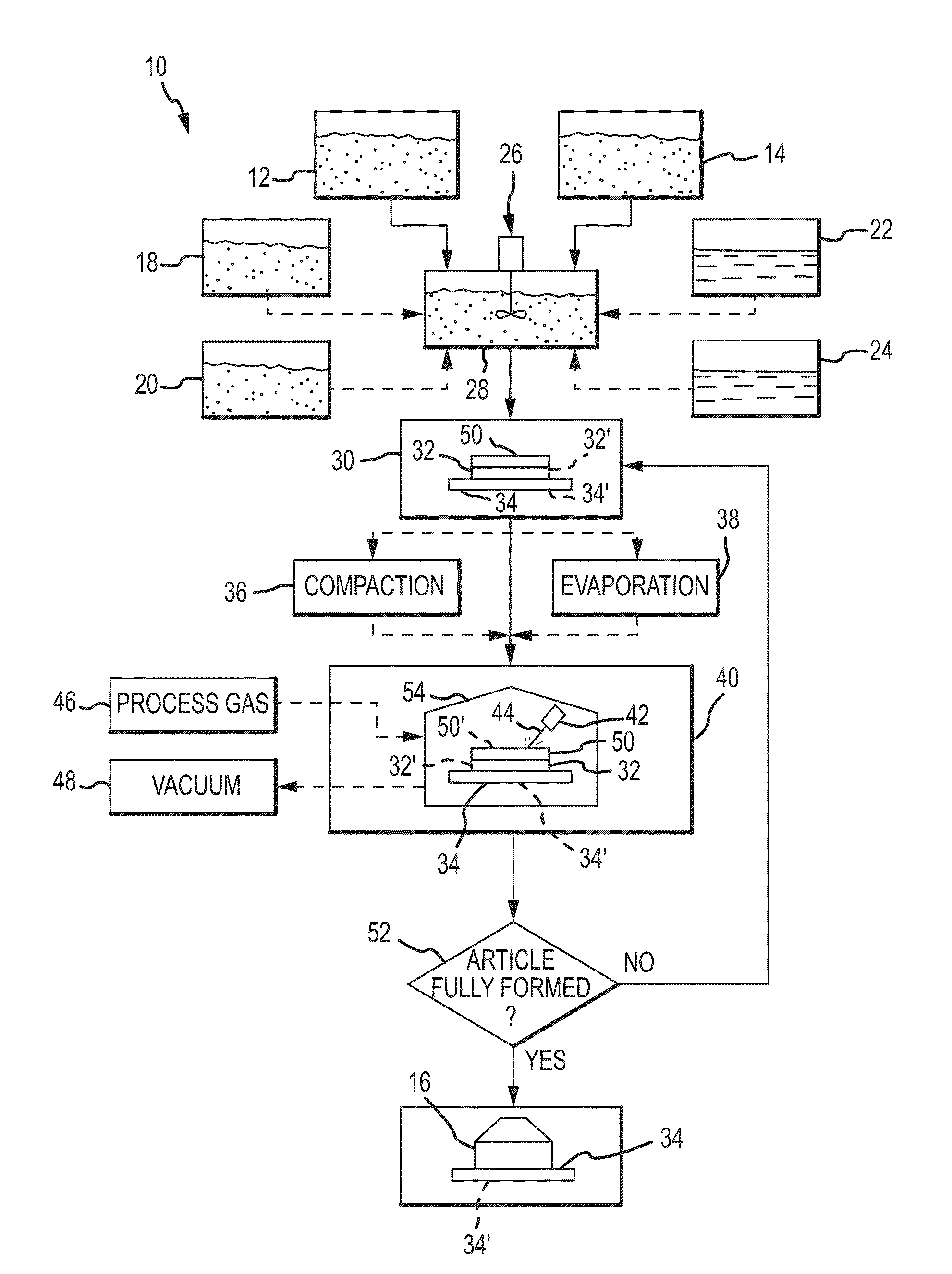
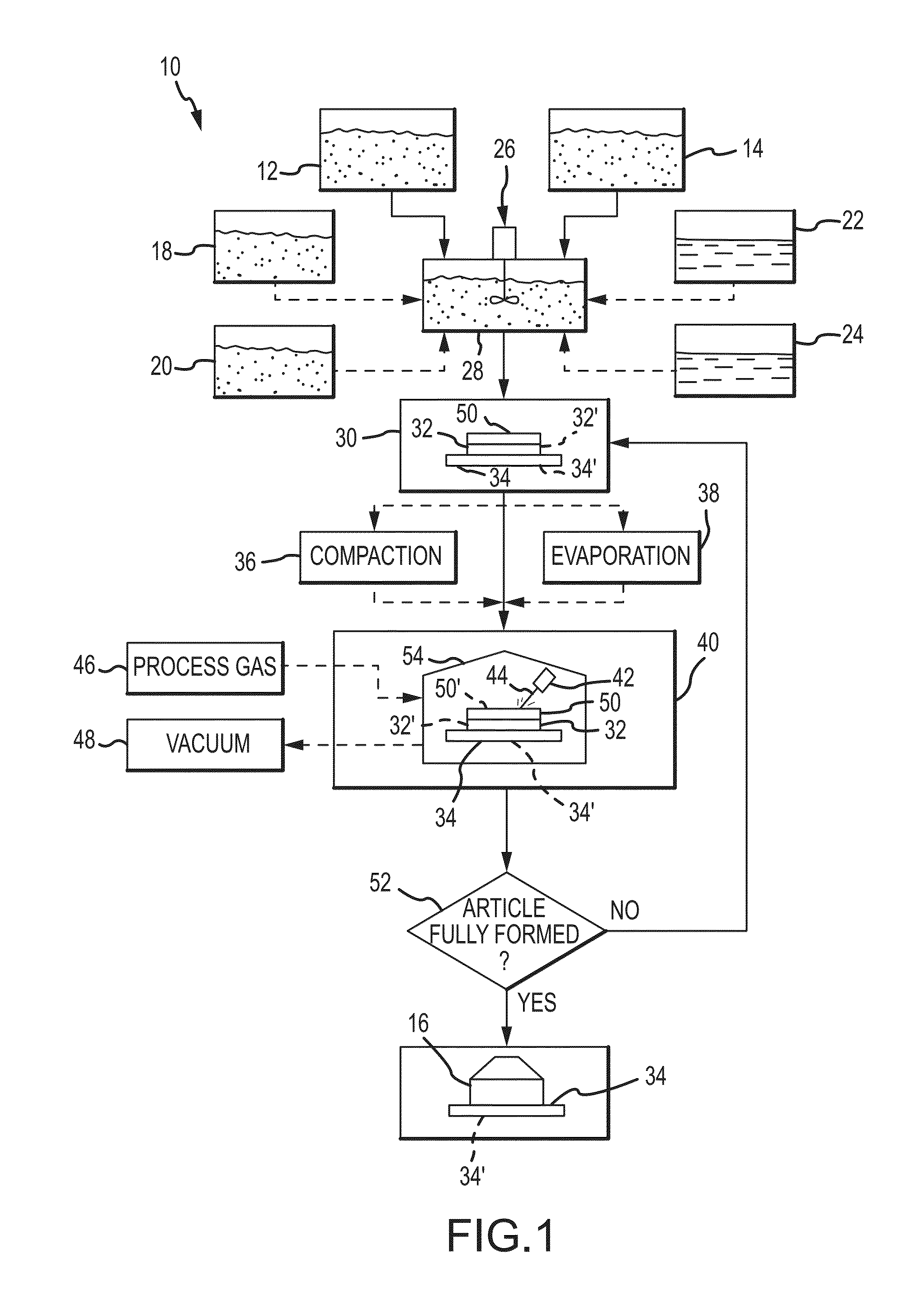
[0073]An exothermically reactive mixture containing by weight 76.8% aluminum, 16.8% titanium, and 6.5% boron carbide powders was designed to produce a product with an aluminum matrix and ceramic reinforcing phases comprising by volume 85% aluminum, 10.75% titanium diboride, and 4.25% titanium carbide. The mixture has a calculated adiabatic reaction temperature of 933 Kelvin. A mixture with a total weight of 4000 g. was prepared by weighing the constituent powders according to the percentages above. The powders were mixed using a motorized tumbler. The mixed powders were then placed in the dispenser tray of an EOS M290 direct metal laser sintering (DMLS) machine, available from EOS of North America, Inc. of Novi, Mich. (US).

[0074]Three dimensional models of articles for manufacture were designed using a computer aided design (CAD) software program and digitally sliced into layers corresponding to the thickness of one layer of powder to be spread. The digital information ...

example 2

(Ti—V)B2, C-85Al—Mg Matrix

[0078]An exothermically reactive mixture containing by weight 75.19% aluminum / 4.5% magnesium alloy powder, 18.23% titanium / 6% aluminum / 4% vanadium powder, and 6.58% boron carbide powder was designed to produce a product with an aluminum / 4.5% magnesium matrix comprising by volume 85% and ceramic reinforcing phases comprising by volume 15% titanium and vanadium diborides and carbides. The mixture has a calculated adiabatic reaction temperature of 933 Kelvin. A mixture with a total weight of 4000 g. was prepared by weighing the constituent powders according to the percentages above. The powders were mixed using a motorized tumbler. The mixed powders were then placed in the dispenser tray of the EOS M290 direct metal laser sintering (DMLS) machine.

[0079]Three dimensional models of articles for manufacture were designed using a computer aided design (CAD) software program and digitally sliced into layers corresponding to the thickness of one layer of powder to b...

example 3

NiTi

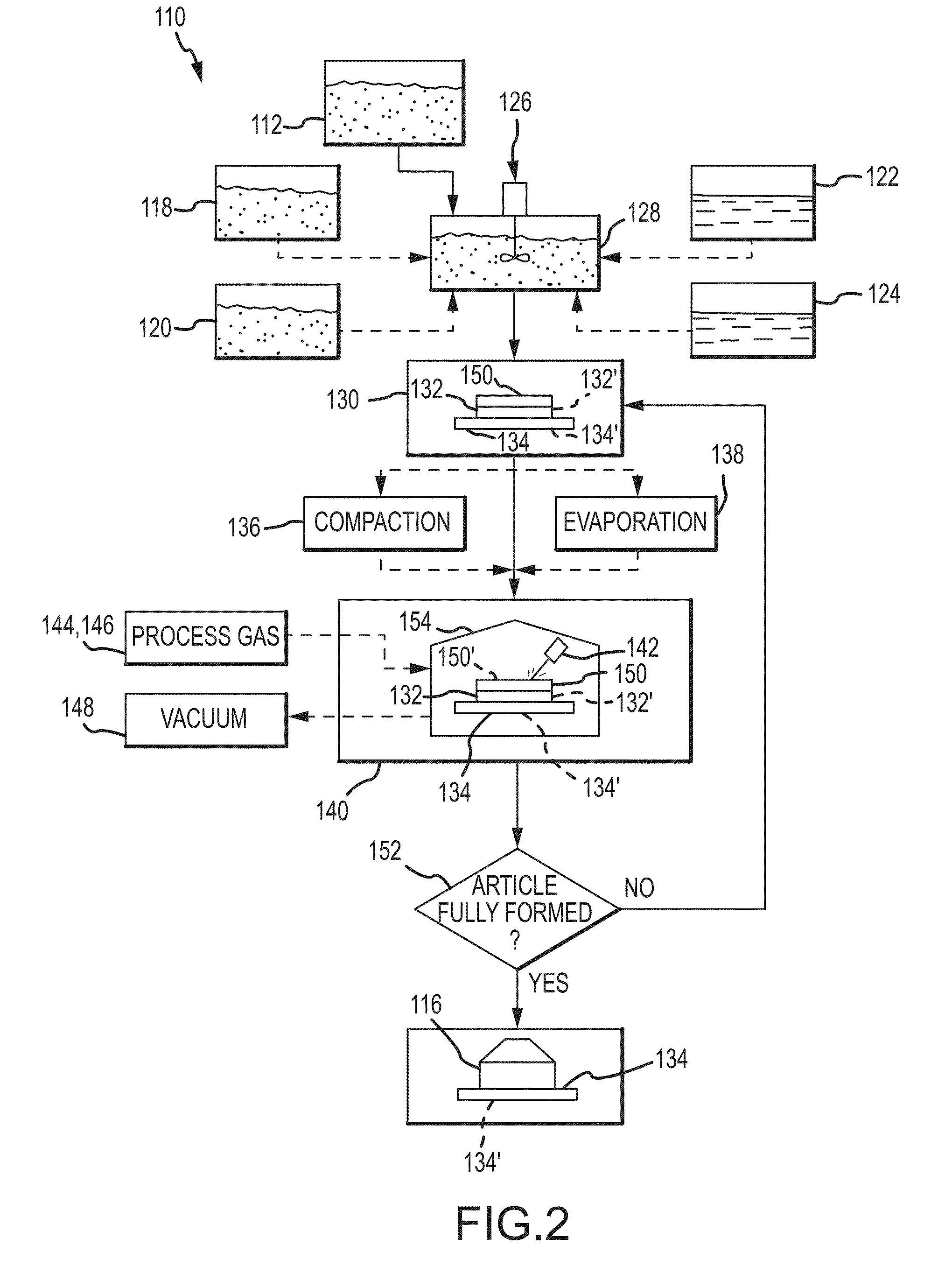
[0082]An exothermically reactive mixture containing by weight 55.5% nickel and 44.5% titanium was designed to produce a product comprised of intermetallic nickel-titanium shape memory alloy. The mixture has a calculated adiabatic reaction temperature of 1438 Kelvin. A mixture with a total weight of 2500 g. was prepared by weighing the constituent powders according to the percentages above. The powders were mixed using a motorized tumbler. The mixed powders were then placed in the dispenser tray of the EOS M290 direct metal laser sintering (DMLS) machine.

[0083]Three dimensional models of articles for manufacture were designed using a computer aided design (CAD) software program and digitally sliced into layers corresponding to the thickness of one layer of powder that will be spread. The digital information was sent to the EOS M290 DMLS machine.

[0084]The processing chamber of the DMLS machine was flooded with argon gas and a layer of the powder mixture having a thickness of about...


PUM

PropertyMeasurementUnit
diameteraaaaaaaaaa
particle sizesaaaaaaaaaa
temperatureaaaaaaaaaa

Abstract

An additive manufacturing method may involve: Providing a first and a second material, the second material capable of reacting with the first material to form a reaction product; forming at least the first material into a first layer; subjecting at least a portion of the first layer to energy in the presence of the second material, the energy being sufficient to initiate a reaction between at least the first and second materials to form a portion of the article, the portion of the article comprising the reaction product; forming a second layer of at least the first material on the first layer; and subjecting at least a portion of the second layer to energy in the presence of the second material, the energy being sufficient to initiate a reaction between the first and second materials to form an additional portion of the article.

Description

CROSS-REFERENCE TO RELATED APPLICATION[0001]This application claims the benefit of U.S. Provisional Patent Application No. 62 / 134,190, filed on Mar. 17, 2015, which is hereby incorporated herein by reference for all that it discloses.TECHNICAL FIELD[0002]The present invention relates to additive manufacturing general and more particularly to methods and systems for performing additive manufacturing with reactive materials.BACKGROUND[0003]Additive manufacturing techniques have been known for decades and are currently used to produce a wide range of parts and articles suitable for any of a wide range of applications. The most common additive manufacturing processes may be grouped into three main categories: Powder bed sintering / melting, extrusion, and directed energy deposition by jetting / wire feed. One type of powder bed sintering / melting technique, which may be referred to as selective laser sintering / melting or direct metal laser sintering, utilizes a laser beam directed energy sou...

Claims


Application Information

Patent Timeline
Patent Type & Authority Applications(United States)
IPC IPC(8): B29C67/00
CPCB33Y10/00B29C67/0081B29C64/165C22C1/10C22C29/08B22F2999/00C04B35/5611C04B35/563C04B35/573C04B35/65C04B35/653C04B2235/665Y02P10/25B22F10/28B22F10/32B22F10/34B22F10/50B22F10/16C22C1/047B22F3/23B29C64/153
Inventor NUECHTERLEIN, JACOB S.ITEN, JEREMY JOSEPH
Owner ELEMENTUM 3D INC
Why Eureka
Try Eureka