System and method for moulding metal parts

a metal part and system technology, applied in the field of system and method for moulding metal parts, can solve the problems of large economic cost, limited design versatility, and large internal defects of sand moulding, and achieve the effects of low internal defect level, reduced cost, and highly versatile parts

Inactive Publication Date: 2017-10-05
AMPO
View PDF0 Cites 0 Cited by
  • Summary
  • Abstract
  • Description
  • Claims
  • Application Information

AI Technical Summary

Benefits of technology

[0011]As a result of the method and system herein described, high-quality parts can be obtained with a low level of internal defects and/or impurities and no volume defects. Furthermore, highly versatile parts may be obtained because part design is not limited with the use of this method.
[0012]Once the dies have been used, they could be reused for producing other parts simply by applying ceramic materials on them, thereby reducing

Problems solved by technology

When producing cast metal parts today, there are a number of methods known in the prior art that allow such production, such as, for example, sand moulding, ceramic moulding, centrifugal casting, etc., but said means have several drawbacks, particularly in relation to the mass production of different parts and the associated economic cost, as well as the need to have several hard-to-store moulds.
For example, sand moulding has the main drawback of being scarcely versatile as regards the design, which is a huge limitation when producing parts with a high degree of specification.
This type of moulding furthermore has the additional drawback of requiring a wooden model for obtaining the sand mould of the part to be produced, meaning that the wooden model will be permanent.
Furthermore, the possibili

Method used


Image

  • System and method for moulding metal parts
  • System and method for moulding metal parts

Examples


Embodiment Construction

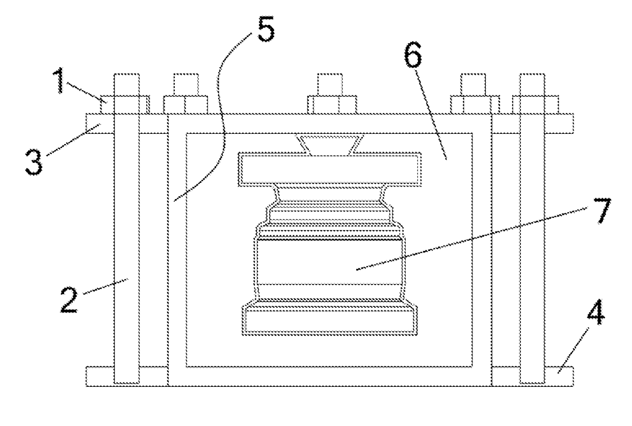
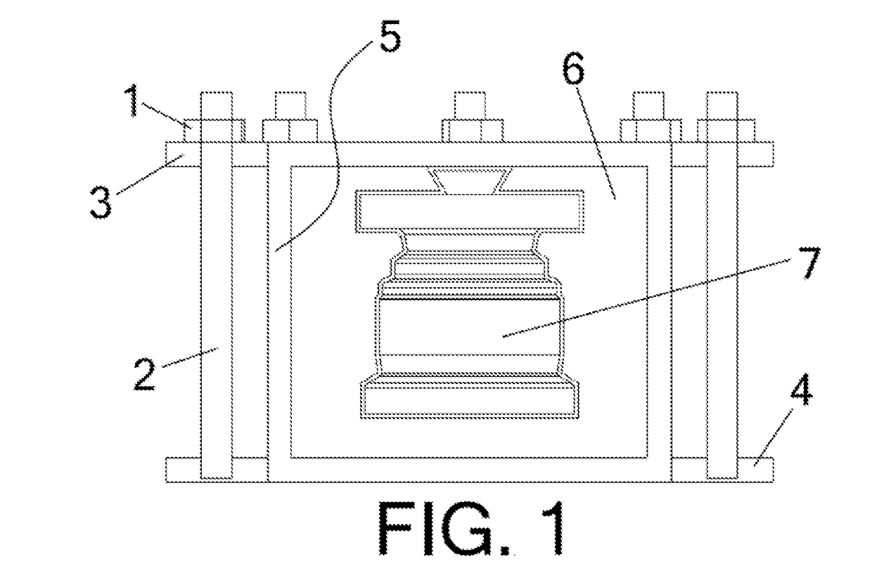
[0017]The attached drawings show a preferred embodiment of the invention. More specifically, it comprises a first metal structure or base (4) which is integrally attached to a rotating machine, said machine rotating the assembly at a high speed, and where said structure (4) is associated with a cover (3) and with a plurality of fastening nuts (1) and bolts (2), and where, in turn, the structure is integrally attached to a cylindrical metal die (5) containing a ceramic mould (7) and hardened sand (6) for filling the die (5).

[0018]The method of moulding ceramic parts includes:[0019]i) In a first step, producing a polystyrene model of the part to be produced; said model can be produced by injecting polystyrene onto an aluminium mould in the event of mass production of parts, or by means of machining a polystyrene block from a polystyrene block for producing unitary parts.[0020]ii) In a second step, introducing the polystyrene model in a liquid ceramic “Milled Zircon®” (zirconium sand) ...


PUM

PropertyMeasurementUnit
Temperatureaaaaaaaaaa

Abstract

A system and method for moulding metal parts having a first metal structure (4) which is integrally attached to a rotating machine, where said structure (4) is associated with a cover (3) and a plurality of fastening elements (1, 2), and where, in turn, the structure (4) is integrally attached to a cylindrical metal die (5) containing a ceramic mould (7) and hardened sand (6) for filling the die (5).

Description

CROSS REFERENCE TO RELATED APPLICATION[0001]This application is a national stage entry of PCT / ES2015 / 070513 filed Jul.1, 2015, under the International Convention claiming priority over Spain Patent Application No. P201431450 filed Oct. 2, 2014.TECHNICAL FIELD[0002]The present invention relates to a system and method for moulding metal parts, the main advantage of which is based on the use of a die having mechanical properties that are good enough to withstand the demands of the centrifugal moulding of large-sized parts.BACKGROUND OF THE PRIOR ART[0003]When producing cast metal parts today, there are a number of methods known in the prior art that allow such production, such as, for example, sand moulding, ceramic moulding, centrifugal casting, etc., but said means have several drawbacks, particularly in relation to the mass production of different parts and the associated economic cost, as well as the need to have several hard-to-store moulds.[0004]For example, sand moulding has the...

Claims


Application Information

Patent Timeline
IPC IPC(8): B22D13/10B22C9/04
CPCB22C9/04B22D13/101B22D13/00B22C1/00
Inventor LARREA LOPEZ, UNAI
Owner AMPO
Why Eureka
Try Eureka