Frame-mounted laser aiming device

a laser aiming device and frame technology, applied in the field of firearm laser aiming devices, can solve the problems of inability to reduce the constant distance of deviation, inconvenient installation and/or replacement, and inability to significantly affect so as to achieve the effect of not significantly affecting the weight or balance of the firearm

Inactive Publication Date: 2012-03-01
SMITH & WESSON
View PDF17 Cites 47 Cited by
  • Summary
  • Abstract
  • Description
  • Claims
  • Application Information

AI Technical Summary

Benefits of technology

[0025]It is an object of the present invention to provide a laser aiming device that is readily installed and/or interchangeable with other laser aiming devices.
[0026]It is an object of the present invention to provide a laser aiming de...

Problems solved by technology

However, since the laser cannot readily be disposed in-line with the firing axis, some divergence is inevitable.
Reducing this constant distance of deviation is difficult in known laser aiming devices.
However, interchanging the laser aiming device can require laser-sight collimation when the laser aiming device is re-attached.
In addition, the mounted laser aiming device often prevents the firearm from being holstered.
However, the grip-integrated laser aiming device is oddly shaped and often requires a holster specific to its design.
Second, the mounted laser aiming device is prone to tampering ...

Method used


Image

  • Frame-mounted laser aiming device
  • Frame-mounted laser aiming device
  • Frame-mounted laser aiming device

Examples


Embodiment Construction

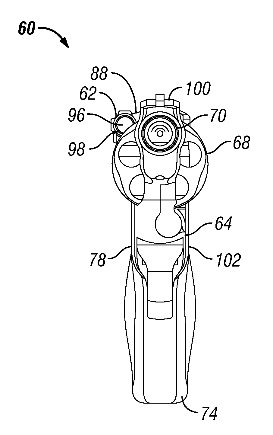
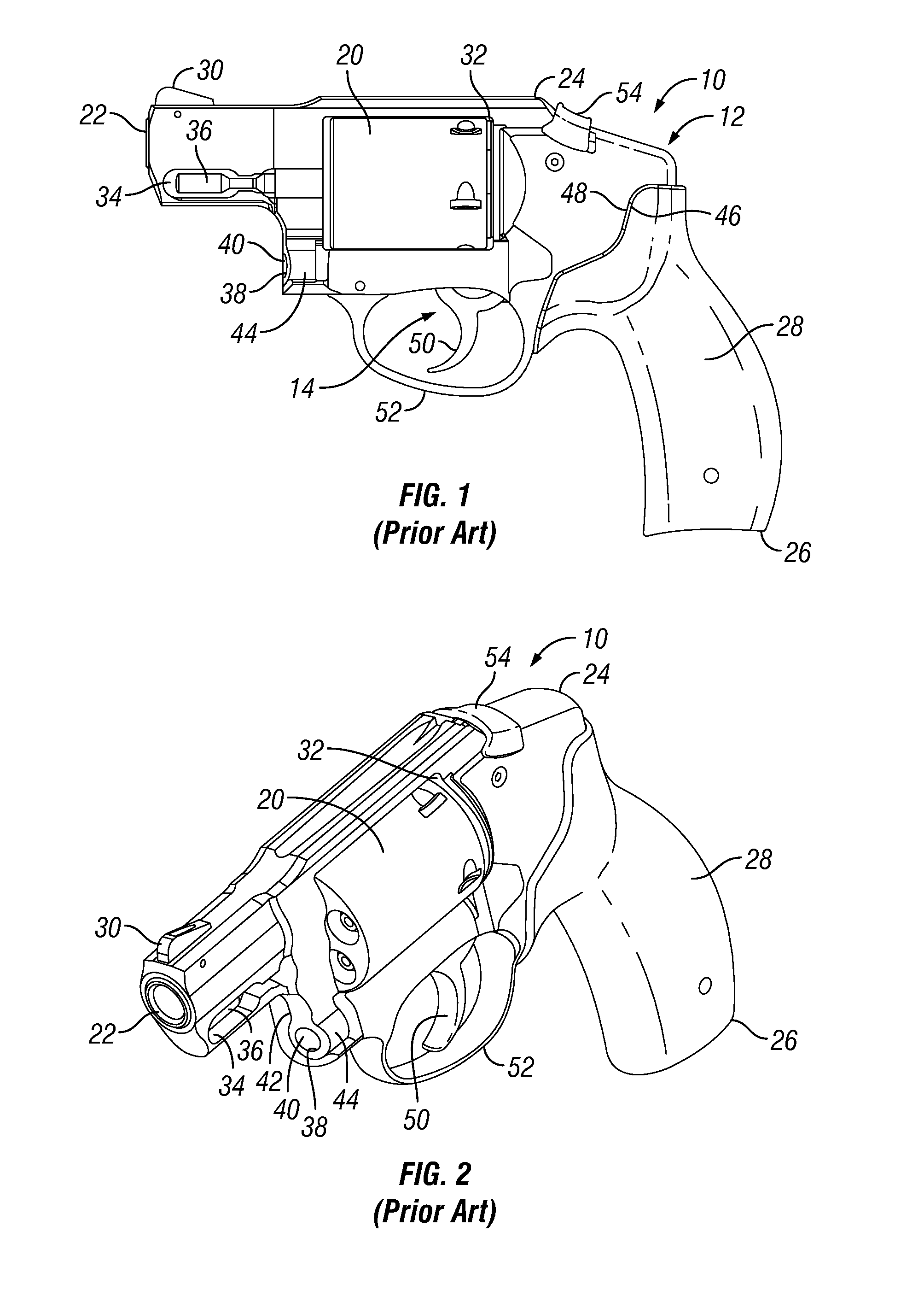
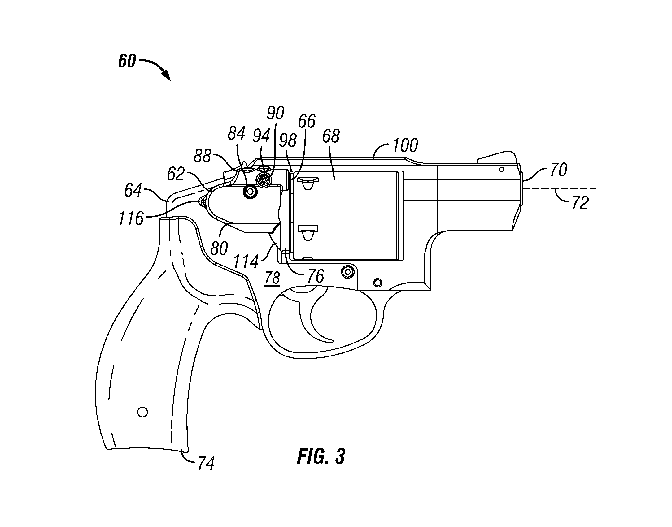
[0039]Referring to FIGS. 1 and 2, one exemplary embodiment of a firearm known in the art is shown generally at 10 and is hereinafter referred to as “firearm 10.” The firearm 10 is, preferably, a revolver that includes a frame 12, a cylinder 20, a barrel 22, and a firing mechanism 14. The operation and structure of the known firearm 10 is described in: U.S. Pat. No. 6,330,761 entitled “BLAST SHIELD APPARATUS AND METHOD OF ASSEMBLY FOR A REVOLVER”; U.S. Pat. No. 6,523,294 entitled “REVOLVER-SAFETY LOCK MECHANISM”; U.S. Pat. No. 7,059,075 entitled “CYLINDER RETAINING MECHANISM”; U.S. Pat. No. 7,254,913 entitled “REVOLVER FOR FIRING HIGH VELOCITY AMMUNITION”; U.S. Pat. No. 7,263,795 entitled “EXTRACTOR FOR A REVOLVER”; U.S. patent application Ser. No. 12 / 760,873 entitled “FIREARM HAVING NONMETALLIC COMPONENTS AND AN AMBIDEXTROUS CYLINDER RELEASE LEVER”; and U.S. patent application Ser. No. 12 / 760,927 entitled “FIREARM HAVING NONMETALLIC COMPONENTS AND AN EXTRACTOR YOKE LOCKUP”, which ar...


PUM


Abstract

A revolver having a frame that defines a rectangular aperture to which a cylinder is mounted, and a laser aiming device that is mounted to the frame, rearward of the rectangular aperture. The laser aiming device is secured to the frame by a fastener that is inserted through an opening defined in a central position of the laser aiming device and into a corresponding hole formed in the frame. The alignment axis of the laser aiming device is proximate the firing axis of the revolver. The laser aiming device is light weight and lies substantially flush against the revolver, between the frame and the cylinder.

Description

CROSS REFERENCE TO RELATED APPLICATION[0001]This application claims the benefit of U.S. Provisional Application No. 61 / 378,153, filed Aug. 30, 2010, entitled “FRAME-MOUNTED LASER AIMING DEVICE”, the aforementioned application being hereby incorporated by reference in its entirety.FIELD OF THE INVENTION[0002]The present invention generally relates to a laser aiming device for a firearm and, more specifically, to a frame-mounted laser aiming device for a revolver.BACKGROUND OF THE INVENTION[0003]Laser aiming devices are attached to firearms to improve the accuracy and precision of the user. In particular, the laser of the laser aiming device is aligned with a firing axis of the firearm and disposed as close to the firing axis as possible to reduce the divergence of the laser and the firing axis. However, since the laser cannot readily be disposed in-line with the firing axis, some divergence is inevitable.[0004]That being the case, if the distance to the target is known (e.g., 7 meter...

Claims


Application Information

Patent Timeline
IPC IPC(8): F41G1/00
CPCF41G1/35
Inventor CURRY, BRETT
Owner SMITH & WESSON
Why Eureka
Try Eureka