

Underwater barricade apparatus
- Summary
- Abstract
- Description
- Claims
- Application Information
AI Technical Summary
Benefits of technology
Problems solved by technology
Method used
Image

Examples
first embodiment
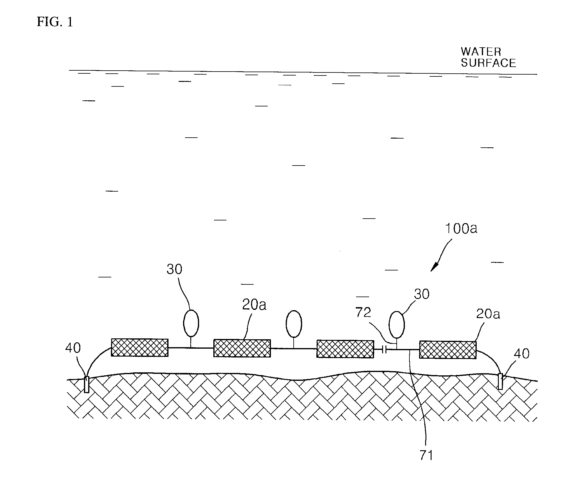
[0038]The underwater barricade apparatus 100a according to the first embodiment of the present invention shown in FIG. 1 employs non-explosive weights 20a as the weights 20.
[0039]The non-explosive weight 20a used may be constituted by a base member of a typical brick, a ceramic body, or a steel member, and the above fiber members wound a plurality of times around the base member. Also, a typical brick, ceramic body, or steel member may have a hole defined therein and used as a weight, or may be coated with rubber or resin and then have holes defined therein and used as a weight (refer to FIG. 3(E)). Further, a hardened fiber body 20a described below may be used.
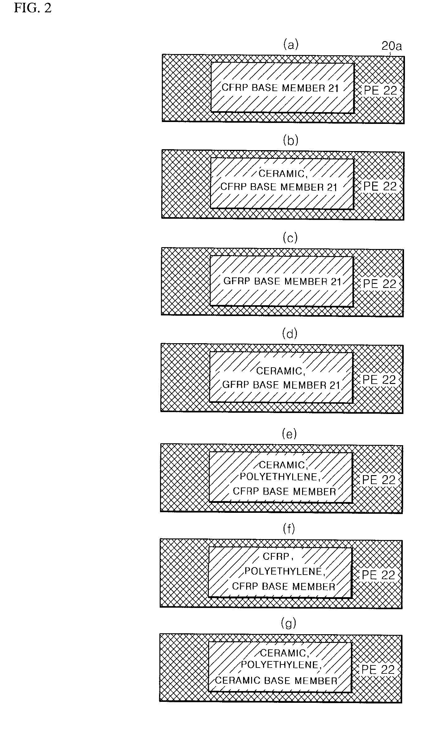
[0040][Reinforced Fiber Body]
[0041]Reinforced fiber body structures of examples of a non-explosive weight 20a according to the present invention, will be described below with reference to FIG. 2.
[0042]For the manufacture of a reinforced fiber body 20a according to an embodiment of the present invention, a fiber member 22 is u...
second embodiment
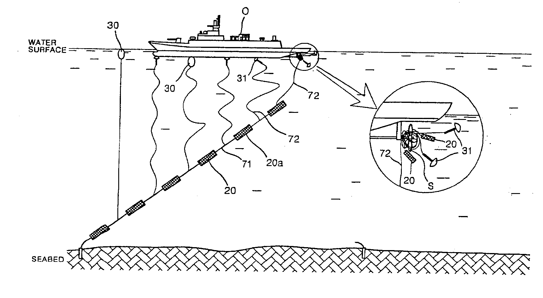
[0081]FIG. 7 is a schematic structural view of an underwater barricade apparatus according to a second embodiment of the present invention. An underwater barricade apparatus 100b according to the second embodiment includes: a plurality of weights 20 connected with a first fiber line 71; a float 30 for floating on a water surface or underwater according to how the weights 20 are laid underwater; and a second fiber line 72 with one end thereof connected to the plurality of weights 20 or the first fiber line 71, and the other end thereof wound and connected to the float 30. The weight 20 is an explosive weight—for example, a depth charge 20b.
[0082]The configurations of the float 30 and the first and second fiber lines 71 and 72 are the same as those of the first embodiment. Also, because the explosive weight 20b of the second embodiment generally has more weight than the non-explosive weight 20a, even if the anchoring means 40 is not included, the underwater barricade apparatus 100b c...
third embodiment
[0109]FIG. 10 is a schematic structural view of an underwater barricade apparatus according to a third embodiment of the present invention. An underwater barricade apparatus 100c according to the third embodiment includes: a plurality of weights 20 connected with a first fiber line 71; a float 30 for floating on a water surface or underwater according to how the weights 20 are laid underwater; and a second fiber line 72 with one end thereof connected to the plurality of weights 20 or the first fiber line 71, and the other end thereof wound and connected to the float 30. The weights 20 include a non-explosive weight 20a and an explosive weight 20b. That is, the explosive weights 20b (for example, depth charges) may be randomly installed between the non-explosive weights 20a (for example, reinforced fiber bodies) that are connected in plurality by the second fiber line 72.
[0110]While FIG. 10 illustrates explosive weights 20b installed for each of the non-explosive weights 20a, the non...
PUM
 Abstract
Description
Claims
Application Information