Method for error detection in a packet-based message distribution system

a message distribution system and error detection technology, applied in the field of packet-based message distribution system error detection, can solve the problems of unsatisfactory uncertainty factor or uncertain state respectively, and achieve the effect of suppressing alarms and suppressing unwanted alarms

Inactive Publication Date: 2013-03-26
NOKIA SIEMENS NETWORKS GMBH & CO KG
View PDF18 Cites 1 Cited by
  • Summary
  • Abstract
  • Description
  • Claims
  • Application Information

AI Technical Summary

Benefits of technology

[0012]With the monitoring method described, it is possible practically to exclude any destabilization of the system due to wiring faults. This increases the reliability of systems in a real application, because the gap between the theoretically achievable availability and the availability actually achieved on site is closed. A risk, which is hard to estimate, is eliminated by the invention. A further advantage of the new method is that it can be carried out without the implementation of additional new hardware, using the hardware already present in the message distribution system.
[0014]It is convenient if changes to the data which describes the topology are made via an operating interface. The topology of the message distribution system can then easily be changed.
[0017]If required, preferably during maintenance, restructuring and extension work activities, the functions for signaling and changing misconfigurations can be disabled. In this way, unwanted alarms from the system during maintenance work will be suppressed.
[0023]As an option, the disconnected nodes and / or system components can then be released for traffic again only when the consistency check has been successful. In this way one would have absolutely no restrictions in the ongoing operations from any wiring problem which arises.

Problems solved by technology

This uncertain state or uncertainty factor respectively is not particularly satisfactory from the point of view of the reliability of the system.

Method used


Image

  • Method for error detection in a packet-based message distribution system
  • Method for error detection in a packet-based message distribution system

Examples


Embodiment Construction

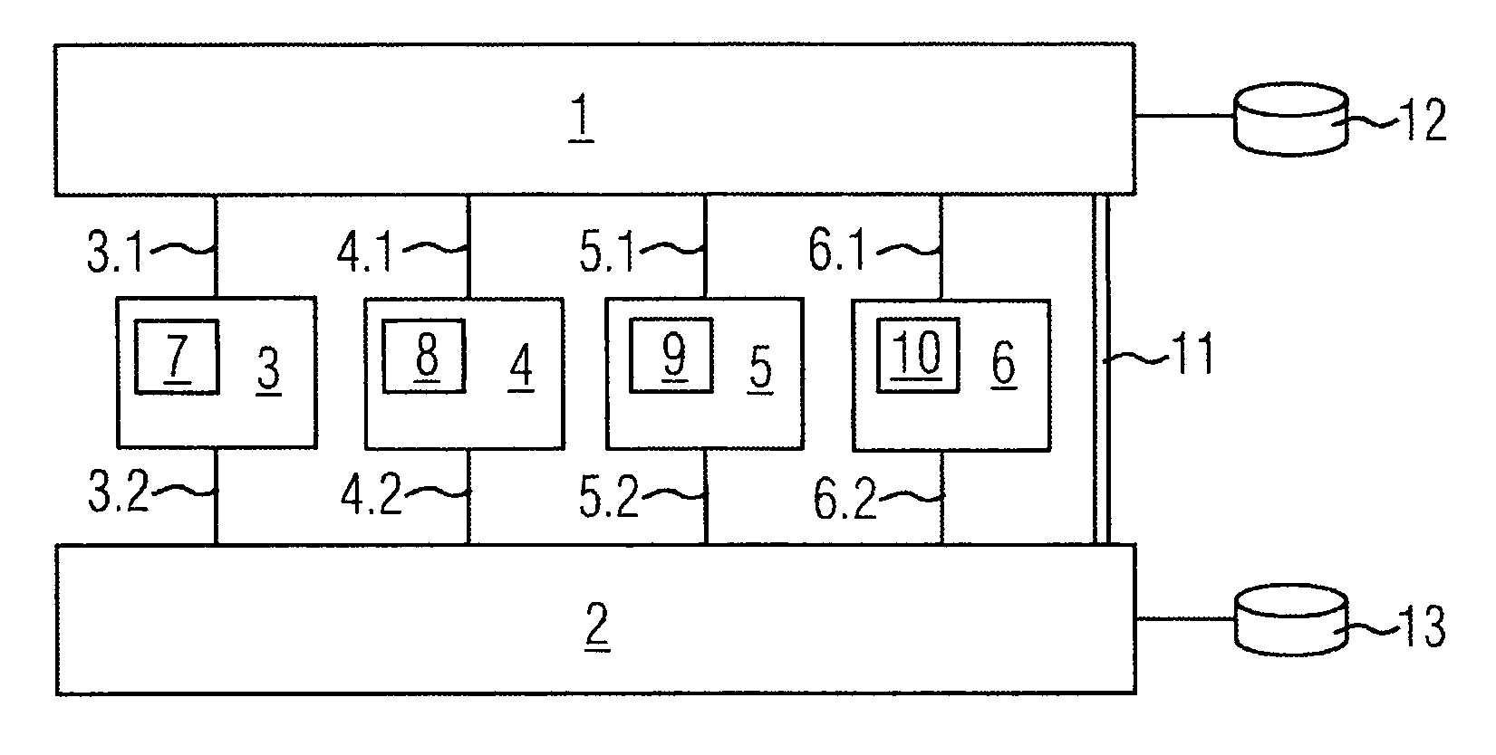
[0035]FIG. 1 shows a redundant communications facility which is correctly wired. Between the switches 1 and 2 are arranged four nodes, indicated by the reference marks 3 to 6, which are connected to the first and second switches 1 and 2 respectively via the links 3.1, 4.1, 5.1, 6.1 and 3.2, 4.2, 5.2, 6.2. Nodes 3 to 6 could, for example, be computers. On the nodes 3 to 6 or via these nodes 3 to 6, as applicable, run various applications 7 to 10. Furthermore, for security purposes the two switches 1 and 2 are directly connected to each other via a cross-link 11.

[0036]The communication facility is connected to the external network via the routers 12 and 13. With this configuration it is possible, by reconfiguration of the IP addresses, to rectify or bypass any individual fault, for example the failure of a link between the switches and of a node, the failure of an Ethernet port or the failure of an entire switch. For example, if one or more Ethernet interfaces on nodes 3 to 6 fail, th...


PUM


Abstract

In one aspect, a method for error detection in a packet-based message distribution system, according to which messages are distributed via a plurality of nodes and other system components, and each node comprises at least two addressable interfaces is provided. For the security of the system, the message distribution paths are designed in a redundant manner and redundancy paths are available in the message distribution system in the event of the breakdown of connections in the message distribution system. The invention topology of the message distribution system is known by the nodes, and the nodes check the accessibility of the other nodes by means of communication tests; interrogate intermediate system components by means of existing interfaces and in terms of the connection status thereof in relation to other nodes and / or system components, and signal optional error configurations, physical errors, and / or missing redundancy paths of the message distribution system.

Description

CROSS REFERENCE TO RELATED APPLICATIONS[0001]This application is the US National Stage of International Application No. PCT / EP2005 / 054649, filed Sep. 19, 2005 and claims the benefit thereof. The International Application claims the benefits of German application No. 102004051167.5 DE filed Oct. 20, 2004, both of the applications are incorporated by reference herein in their entirety.FIELD OF INVENTION[0002]The invention relates to a method for error detection in a packet-based message distribution system, in which messages are distributed via a plurality of nodes and other system components, and each node has at least two addressable interfaces, and for the security of the system the message distribution paths are designed with redundancy, and redundancy paths are available in the event of the failure of one or more links between nodes and / or system components in the message distribution system.BACKGROUND OF INVENTION[0003]The correct functioning of communication facilities which ar...

Claims


Application Information

Patent Timeline
Patent Type & Authority Patents(United States)
IPC IPC(8): G08C15/00H04L12/28
CPCH04L69/40H04L69/14
Inventor HOF, JONASLOBIG, NORBERTTEGELER, JURGENTINNACHER, MICHAELWALLNER, DIETER
Owner NOKIA SIEMENS NETWORKS GMBH & CO KG
Why Eureka
Try Eureka