

Large transmissions on packetized data bus
a data bus and large-format technology, applied in the field of data transmission systems, can solve problems such as performance problems with the interface itself, and achieve the effect of revealing performance problems
- Summary
- Abstract
- Description
- Claims
- Application Information
AI Technical Summary
Benefits of technology
Problems solved by technology
Method used
Image

Examples
embodiment 100
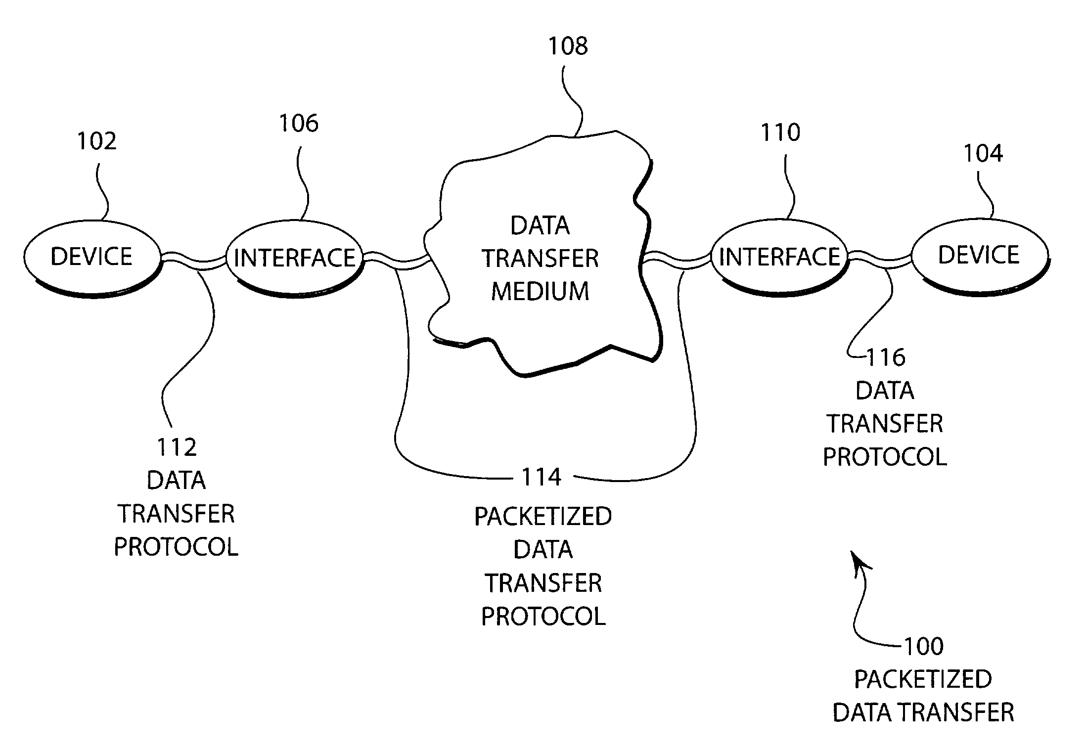
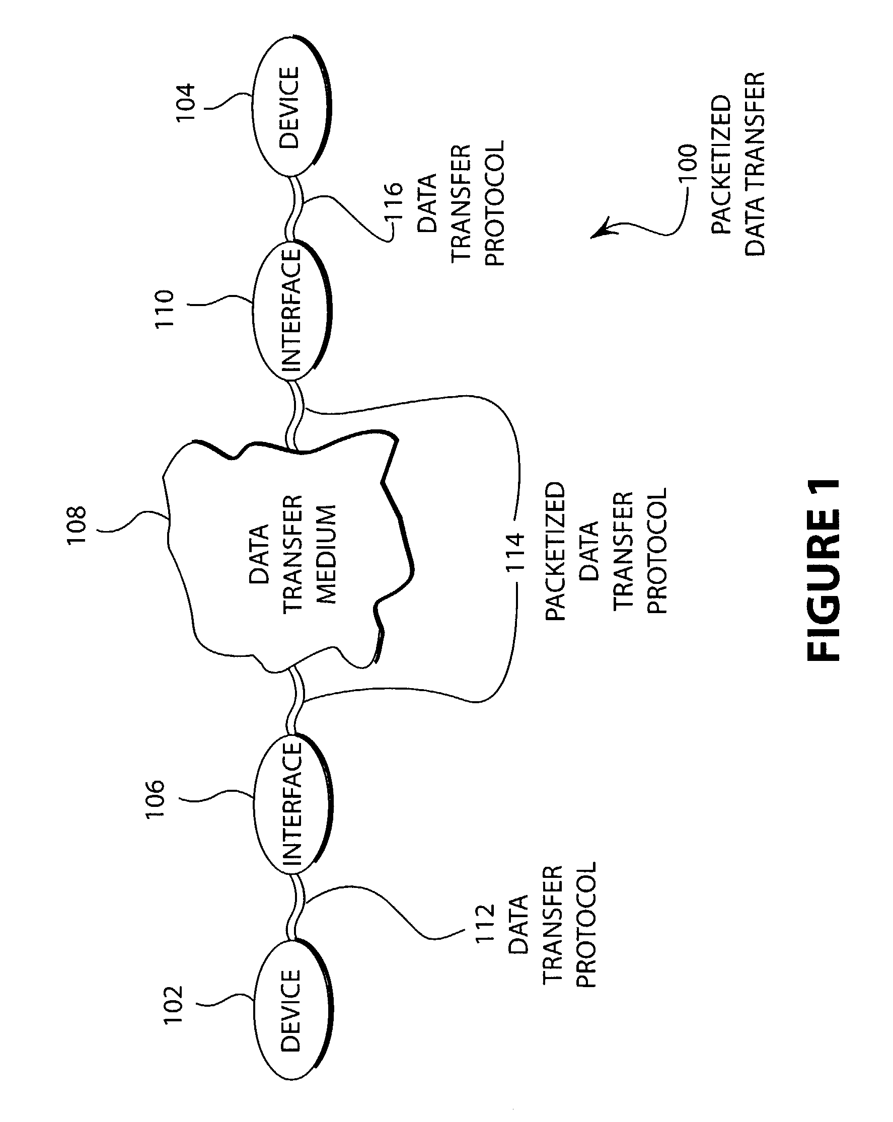
[0018]FIG. 1 illustrates an embodiment 100 of a packetized data transfer system. The devices 102 and 104 are connected to communicate. The device 102 connects to an interface 106 that connects through a data transfer medium 108 and a second interface 110 to the device 104. The device 102 communicates with the interface 106 with a data transfer protocol 112. The interface 106 communicates to interface 110 with a packetized data transfer protocol 114. The interface 110 communicates with device 104 through data transfer protocol 116.
[0019]The devices 102 and 104 may be computers, peripherals, storage devices, appliances, or any other device that may send or receive data. An example may be individual computers, computer peripherals, networked peripherals or appliances, or any other device capable of communicating with a packetized data transfer protocol.
[0020]The data transfer medium 108 may be a cable, as in the case of a SCSI interface, or may be a complex network such as the Internet...
embodiment 200
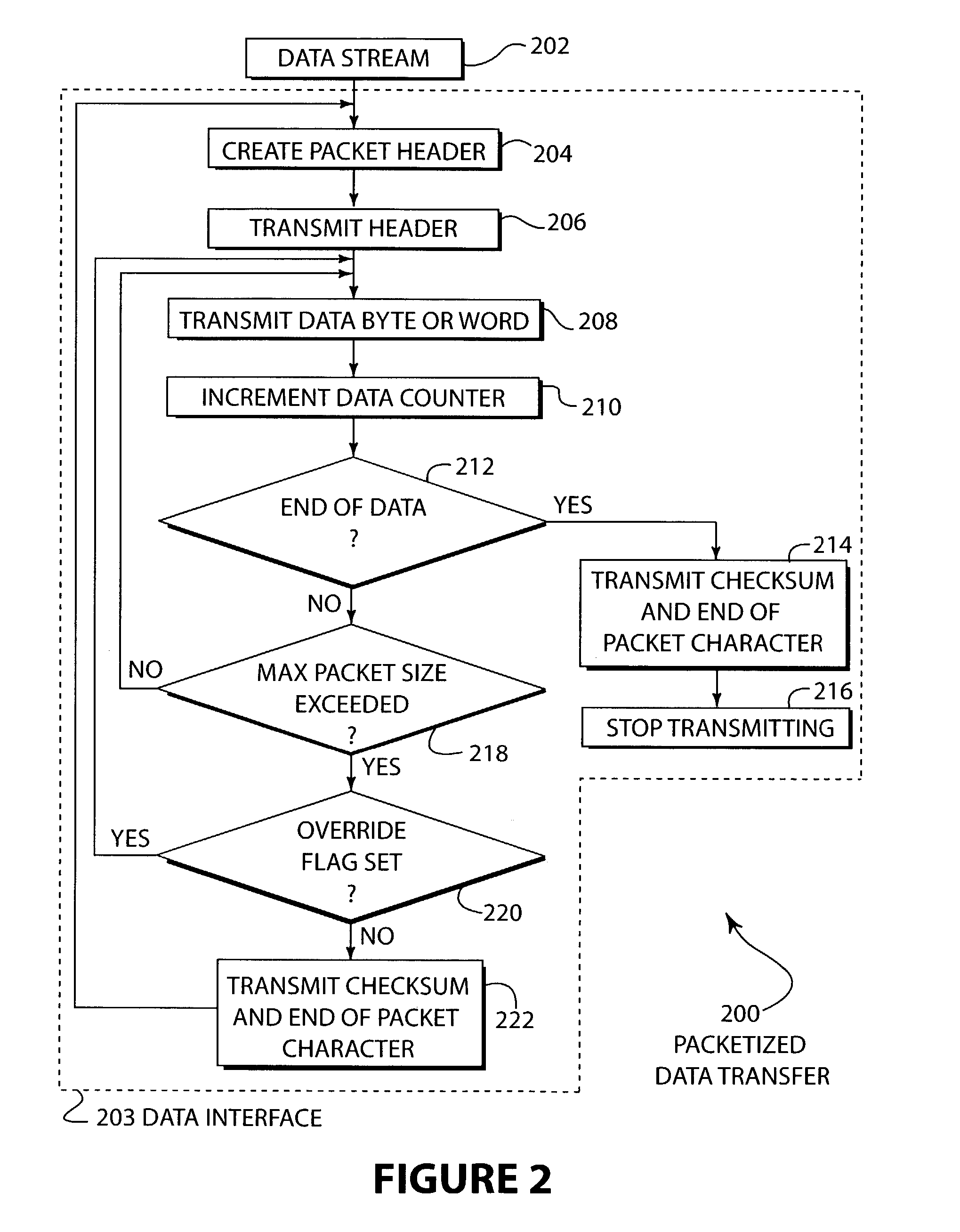
[0026]FIG. 2 illustrates a flow diagram of an embodiment 200 of a packetized data transfer. A data stream in block 202 enters the data interface in block 203. A packet header is created in block 204 and transmitted in block 206. A data byte or word is transmitted in block 208 and a counter incremented in block 210. If the end of data is reached in block 212, the footer of the packet, possibly including a checksum and other characters, is transmitted in block 214 and the transmission stops in block 216. If the end of data is not reached in block 212, the maximum size of the packet is checked in block 218. If the maximum size of the packet is not exceeded in block 218, then another data byte or word is transmitted in block 208. If the maximum packet size is exceeded in block 218 and the override flag is set in block 220, the process returns to block 208 and another data byte is transmitted. If the override flag is not set in block 220, the end of packet information is transmitted in b...
embodiment 300
[0028]FIG. 3 illustrates a flow diagram of an embodiment 300 of a debugging method for a packetized data transfer protocol. A data pattern is created in block 302. The override bit is turned on in block 304 and the data pattern is transmitted in block 306. The transmitted data is compared to the received data in block 308. If an error was found in block 310, the root cause is determined in block 312, corrected in block 314, and the process is repeated. If no errors were determined in block 310, the process halts.
[0029]The embodiment 300 illustrates a mechanism whereby large patterns of data may be useful in helping to uncover problems with an interface design. Those skilled in the art will appreciated that the override bit may be used for other functions, such as for characterization of the interface or for manufacturing defect testing or for other functions.
PUM
 Abstract
Description
Claims
Application Information