Flat heat pipe with internal supporting element

Inactive Publication Date: 2012-03-01
FU ZHUN PRECISION IND SHENZHEN +1
View PDF6 Cites 9 Cited by
  • Summary
  • Abstract
  • Description
  • Claims
  • Application Information

AI Technical Summary

Problems solved by technology

However, the housing is thin and prone to sustain deformation from external force.
When this happens, the normal functions and capabilities of the flat heat pipe are liable to be adversely affected.

Method used


Image

  • Flat heat pipe with internal supporting element
  • Flat heat pipe with internal supporting element
  • Flat heat pipe with internal supporting element

Examples


Embodiment Construction

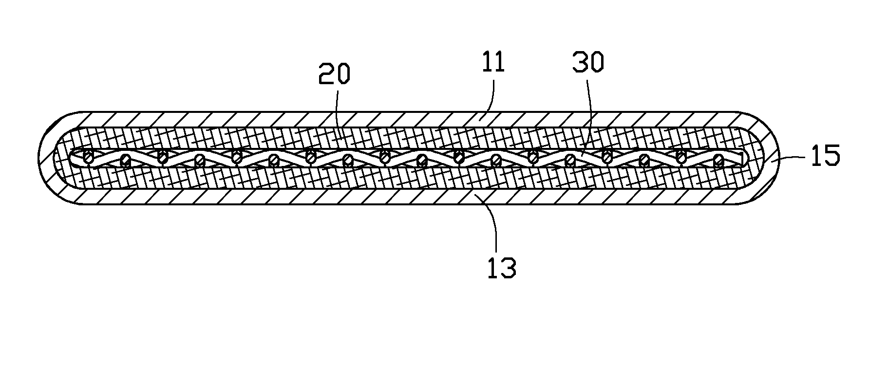
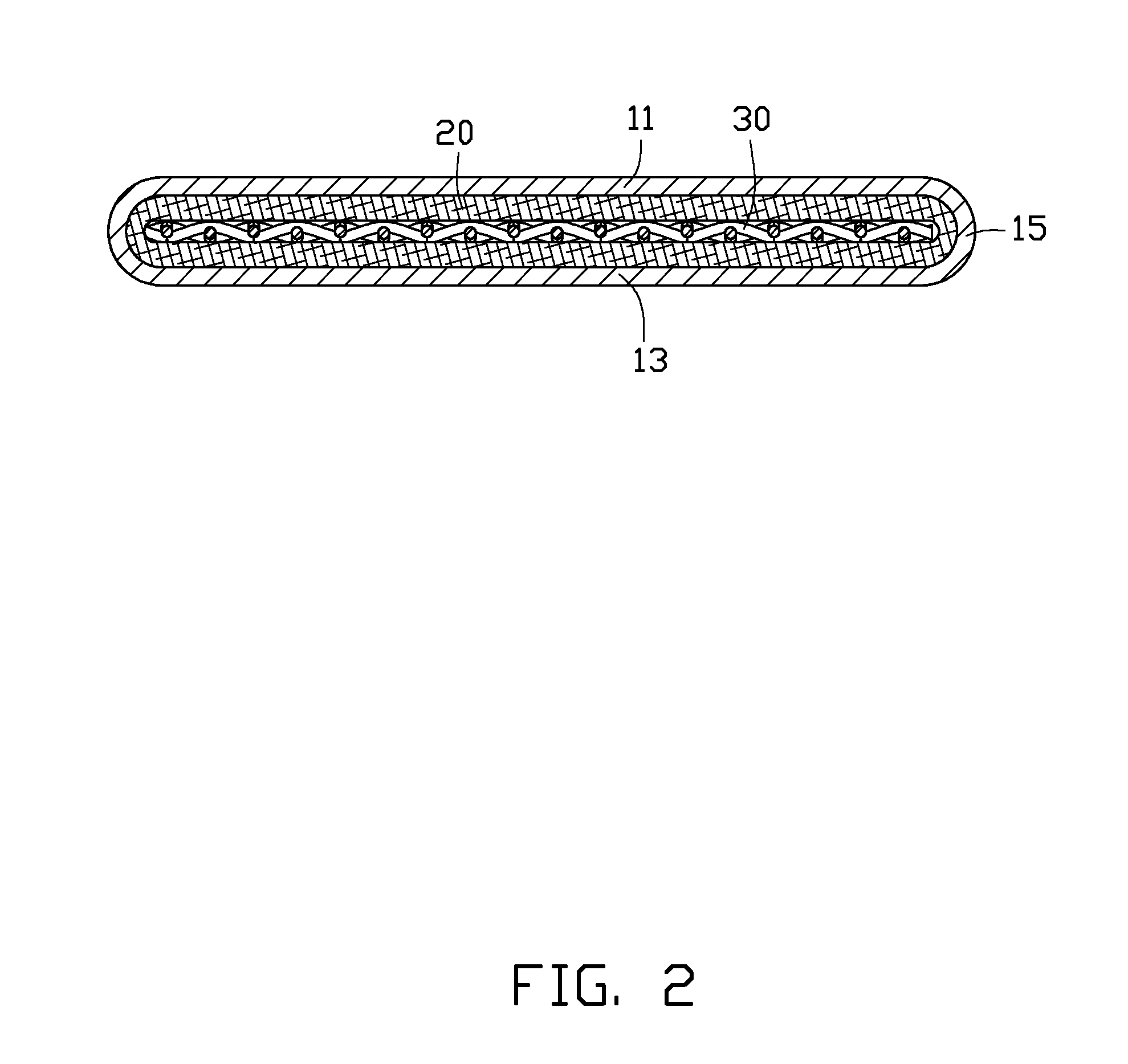
[0009]Referring to FIGS. 1-2, a flat heat pipe of the present embodiment includes a flat housing 10, a wick 20 attached to an inner surface of the housing 10, a supporting element 30 enclosed by the wick 20 and biasing the wick 20 against the housing 10, and a working fluid (not shown) contained in the housing 10.

[0010]The working fluid is water, alcohol or other material having a relatively low boiling point, which can easily change to vapor when absorbing heat from the housing 10.

[0011]The housing 10 has both ends thereof hermetically sealed, and maintains a substantial vacuum therein. In the present embodiment, the housing 10 is made from a single body of material which is hermetically crimped at both ends thereof. The housing 10 is made of a high heat conductivity material such as copper. The housing 10 includes an elongated top plate 11, an elongated bottom plate 13, and two curved connecting plates 15. The bottom plate 13 is spaced from and parallel to the top plate 11. The tw...


PUM


Abstract

An exemplary flat heat pipe includes a flat housing, a wick, a working fluid, and a supporting element. The wick is attached to an inner surface of the housing. The working fluid is contained in the housing. The supporting element is a woven screen made of metal wires and a plurality of through holes is defined therein. The supporting element is enclosed by the wick and opposite sides thereof bias the wick against opposite portions of the housing.

Description

BACKGROUND[0001]1. Technical Field[0002]The present disclosure relates to heat dissipation, and more particularly to a flat heat pipe.[0003]2. Description of Related Art[0004]A commonly used flat heat pipe includes a flat housing, a wick attached to an inner surface of the housing, and a working fluid contained in the housing. However, the housing is thin and prone to sustain deformation from external force. When this happens, the normal functions and capabilities of the flat heat pipe are liable to be adversely affected.[0005]It is thus desirable to provide a flat heat pipe which can overcome the described limitations.BRIEF DESCRIPTION OF THE DRAWINGS[0006]FIG. 1 is an assembled view of a flat heat pipe of an embodiment of the present disclosure.[0007]FIG. 2 is a cross section of the flat heat pipe of FIG. 1, taken along line II-II thereof.[0008]FIG. 3 is an isometric view of a supporting element of the heat pipe of FIG. 2.DETAILED DESCRIPTION[0009]Referring to FIGS. 1-2, a flat he...

Claims


Application Information

Patent Timeline
IPC IPC(8): F28D15/04
CPCF28D15/0233F28F2240/00F28D15/046
Inventor ZHOU, ZHI-YONGZHANG, SHENG-CHAOZHANG, JUN
Owner FU ZHUN PRECISION IND SHENZHEN
Why Eureka
Try Eureka