Webbing winding device

a winding device and webbing technology, applied in the direction of vehicle safety belts, belt retractors, vehicle components, etc., to achieve the effect of increasing the number of coils and increasing the difference in limiting the rotational torqu

Active Publication Date: 2012-03-01
KK TOKAI RIKA DENKI SEISAKUSHO
View PDF11 Cites 3 Cited by
  • Summary
  • Abstract
  • Description
  • Claims
  • Application Information

AI Technical Summary

Benefits of technology

[0011]In consideration of the above circumstances, an object of the present invention is to provide a webbing winding device that is capable of increasing a difference in limiting torques of rotation between a spring and a rotary member between when the spring is not wound on the rotary member and when the spring is wound on the rotary member, without increasing a number of coils of the spring.

Problems solved by technology

However, in this webbing winding device, a limiting torque between a torsion coil spring and an adapter when the torsion coil spring is not tightly wound on the adapter needs to be small, while a limiting torque between the torsion coil spring and the adapter when the torsion coil spring is tightly wound on the adapter needs to be large.

Method used


Image

  • Webbing winding device
  • Webbing winding device
  • Webbing winding device

Examples


Embodiment Construction

Structure of Present Exemplary Embodiment

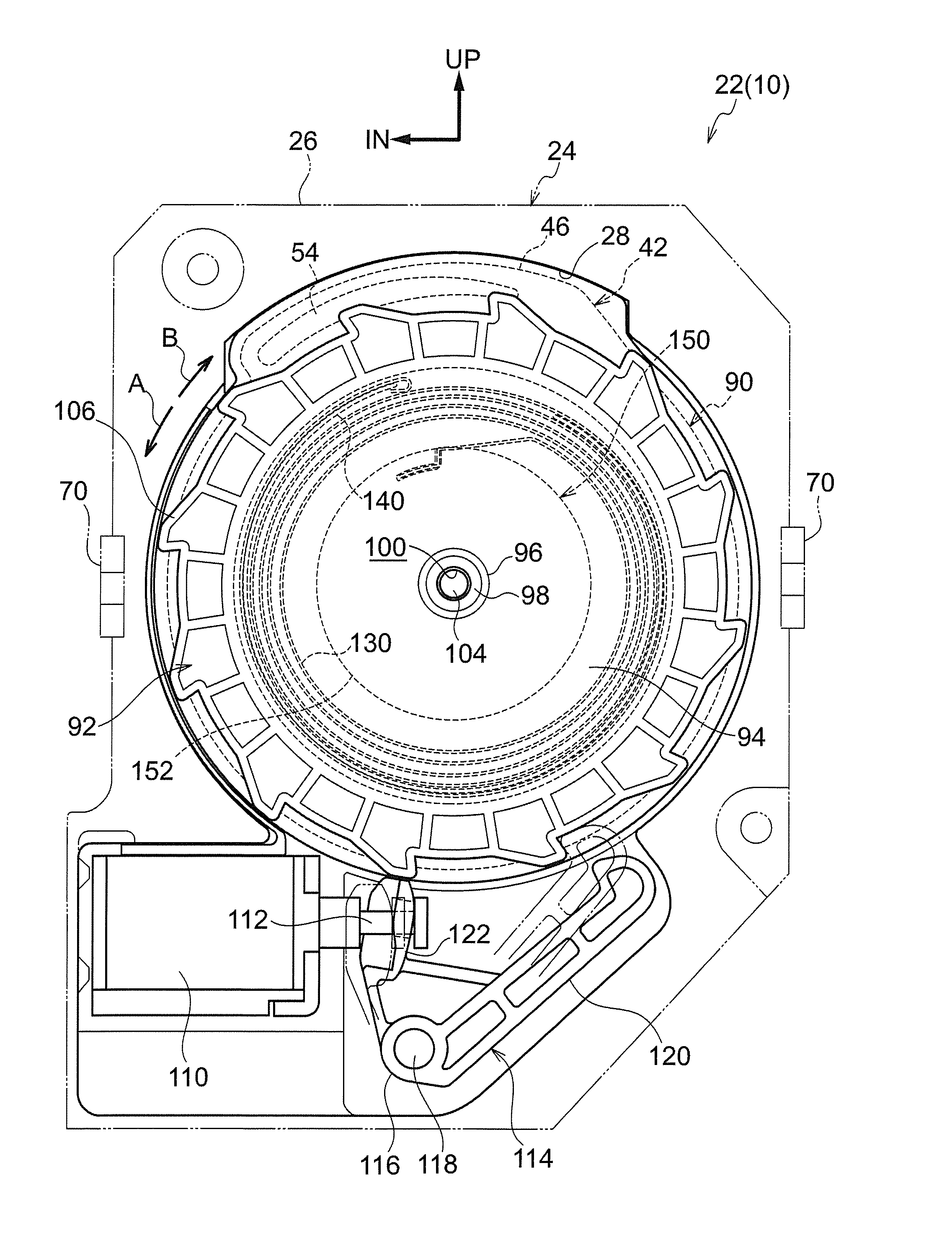
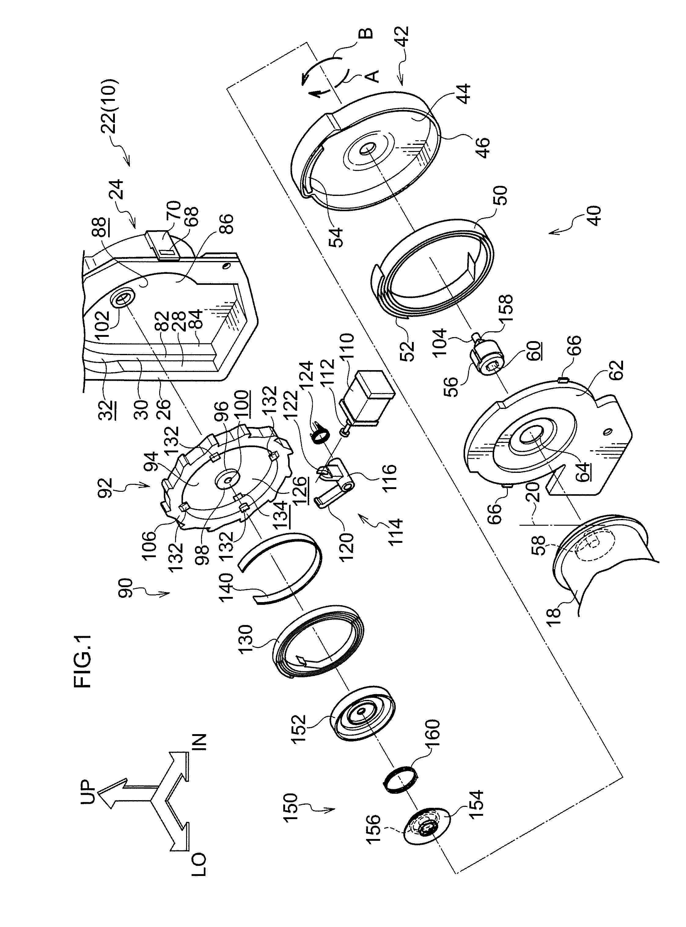
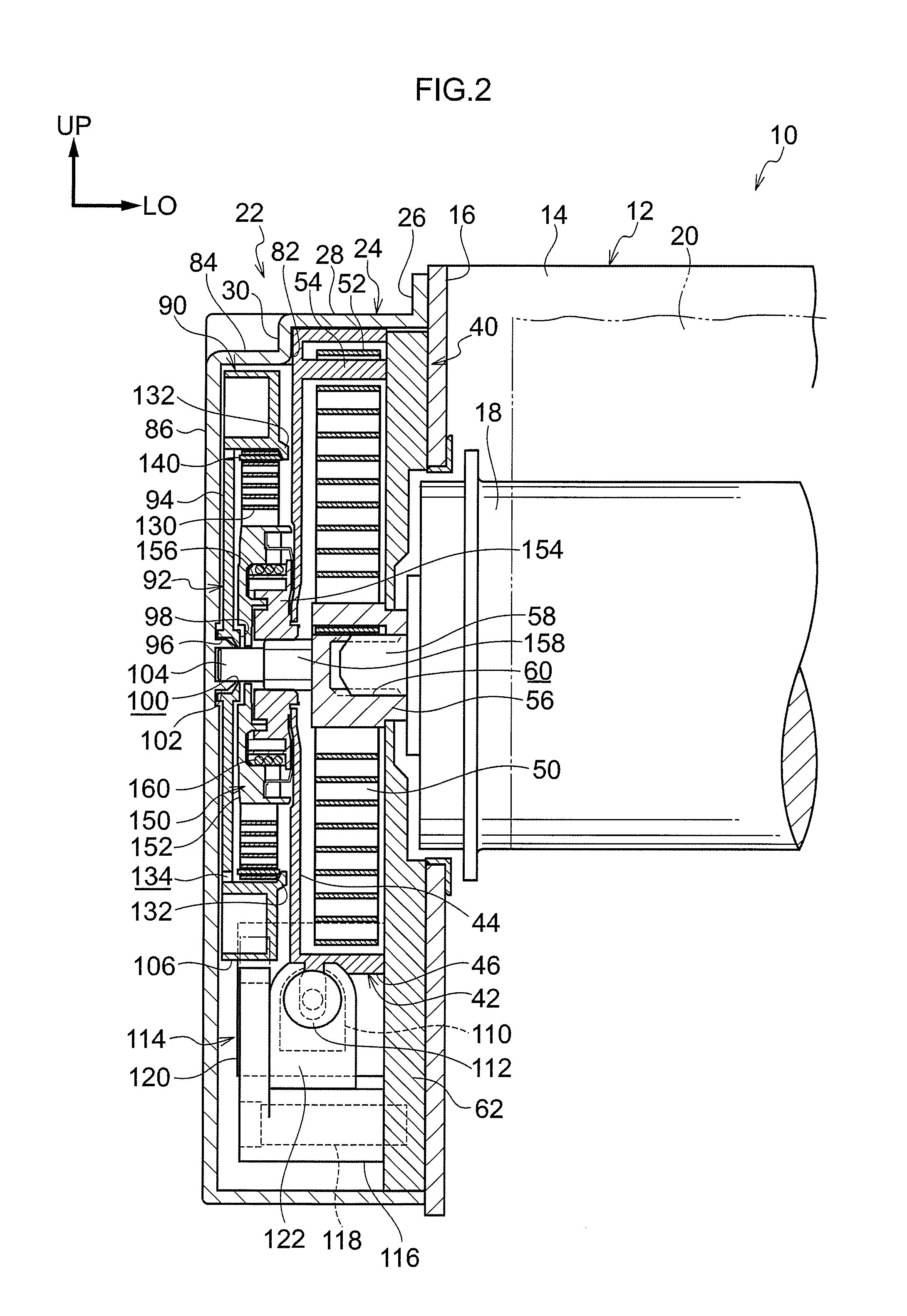
[0031]FIG. 1 shows principal portions of a webbing winding device (a webbing retractor) 10 relating to an exemplary embodiment of the present invention in an exploded perspective diagram viewed from one side in a vehicle front-rear direction and from a vehicle width direction inner side. FIG. 2 illustrates the principal portions of the webbing winding device 10 in a sectional diagram viewed from the vehicle width direction outer side.

[0032]As illustrated in FIG. 2, the webbing winding device 10 is provided with a frame 12. The frame 12 is provided with a rear plate 14. A leg plate 16 is extended to one side in a thickness direction of the rear plate 14 from one width direction end portion of the rear plate 14 (a vehicle front-rear direction other side). A leg plate (not illustrated) is extended in the direction of extension of the leg plate 16 from the rear plate 14, from a width direction other end portion of the rear plate 14 (the vehicle f...


PUM


Abstract

A difference in limiting torques of rotation between a spring and a rotary member is increased without increasing a number of coils of the spring. In a webbing winding device, an outer diameter of a clutch wall of a clutch wheel increases from a flange side to a stopping flange side of the clutch wall. When a clutch spring is tightly wound on the clutch wall, the clutch spring is subjected to a movement force toward the stopping flange side. Thus, a winding force of the clutch spring onto the clutch wall is effectively increased. Therefore, a difference in limiting torques of rotation between the clutch spring and the clutch wheel between when the clutch spring is not tightly wound on the clutch wall and when it is wound on the clutch wall is increased, without increasing a number of coils of the spring.

Description

CROSS-REFERENCE TO RELATED APPLICATION[0001]This application claims priority under 35 USC 119 from Japanese Patent Application No. 2010-191301 filed Aug. 27, 2010, the disclosure of which is incorporated by reference herein.BACKGROUND OF THE INVENTION[0002]1. Field of the Invention[0003]The present invention relates to a webbing winding device that transmits urging force to a spool on which a webbing that is applied to an occupant of a vehicle is wound and unwound.[0004]2. Related Art[0005]In a webbing winding device recited in Japanese Patent Application Laid-Open (JP-A) No. 2001-233175, adapters (a first adapter and a second adapter) are provided between a spool and a spiral coil spring, and torsion coil springs (a first torsion coil spring and a second torsion coil spring) are provided at outer peripheries of the adapters.[0006]When the first torsion coil spring is tightly wound on the outer peripheries of the first adapter and the second adapter, turning between the first torsio...

Claims


Application Information

Patent Timeline
Patent Type & Authority Applications(United States)
IPC IPC(8): B60R22/34
CPCB60R2022/446B60R22/44
Inventor OSAKI, TAKAHIRO
Owner KK TOKAI RIKA DENKI SEISAKUSHO
Why Eureka
Try Eureka