Laminar flow monitor

a technology of laminar flow and monitor, which is applied in the direction of structural/machine measurement, analog and hybrid computing, computation using non-denominational number representation, etc., can solve the problems of premature transition to turbulence, and achieve the effect of little or no weight, drag or cost penalty, and rapid and simultaneous perturbation of airflow

Active Publication Date: 2012-03-01
AIRBUS OPERATIONS LTD
View PDF7 Cites 7 Cited by
  • Summary
  • Abstract
  • Description
  • Claims
  • Application Information

AI Technical Summary

Benefits of technology

[0006]The airflow may be perturbed by any suitable means. For example the airflow may be perturbed by vibrating the aerodynamic surface using a device installed within or below the surface. Alternatively the airflow may be perturbed by transmitting an acoustic signal from an acoustic transducer parallel with the surface through the airflow adjacent the surface. However most preferably the airflow is perturbed by heating the surface. This has the advantage that it enables the airflow to be perturbed quickly and simultaneously over a wide area.
[0007]The airflow may be perturbed by the operation of an ice protection system which either removes or prevents the build up of ice on the surface. The ice protection system may for example heat the surface using an electro-thermal heating pad or using bleed air, or it may operate by pumping glycol from below the surface through a series of perforations in the surface. The use of an ice protection system is advantageous since many conventional aircraft already have such systems installed to remove ice from the surface or prevent ice building up on the surface. In conventional aircraft such systems are only operated during ascent and / or descent flight phases (typically under 7500 m) but when employed in the context of the present invention the ice protection system is typically also operated during a cruise phase (typically over 7500 m) to perturb the air flow and enable a measurement to be made. The use of an ice protection system enables the invention to be implemented with little or no weight, drag or cost penalty.
[0012]The method may be performed only once during a flight, but more typically each step of the method is repeated to provide a series of estimates of the performance of the surface during a flight, either during a single non-perturbed measurement period or over a succession of such periods. These estimates can then be used in a number of ways to monitor the performance of the surface: for instance an average value can be taken to minimise random error, or the rate of change of the estimates may be monitored in order to detect an abrupt deterioration in the performance of the surface.

Problems solved by technology

However, laminar flow is very sensitive to small surface imperfections and distortion which can result in premature transition to turbulence.

Method used


Image

  • Laminar flow monitor
  • Laminar flow monitor
  • Laminar flow monitor

Examples


Embodiment Construction

)

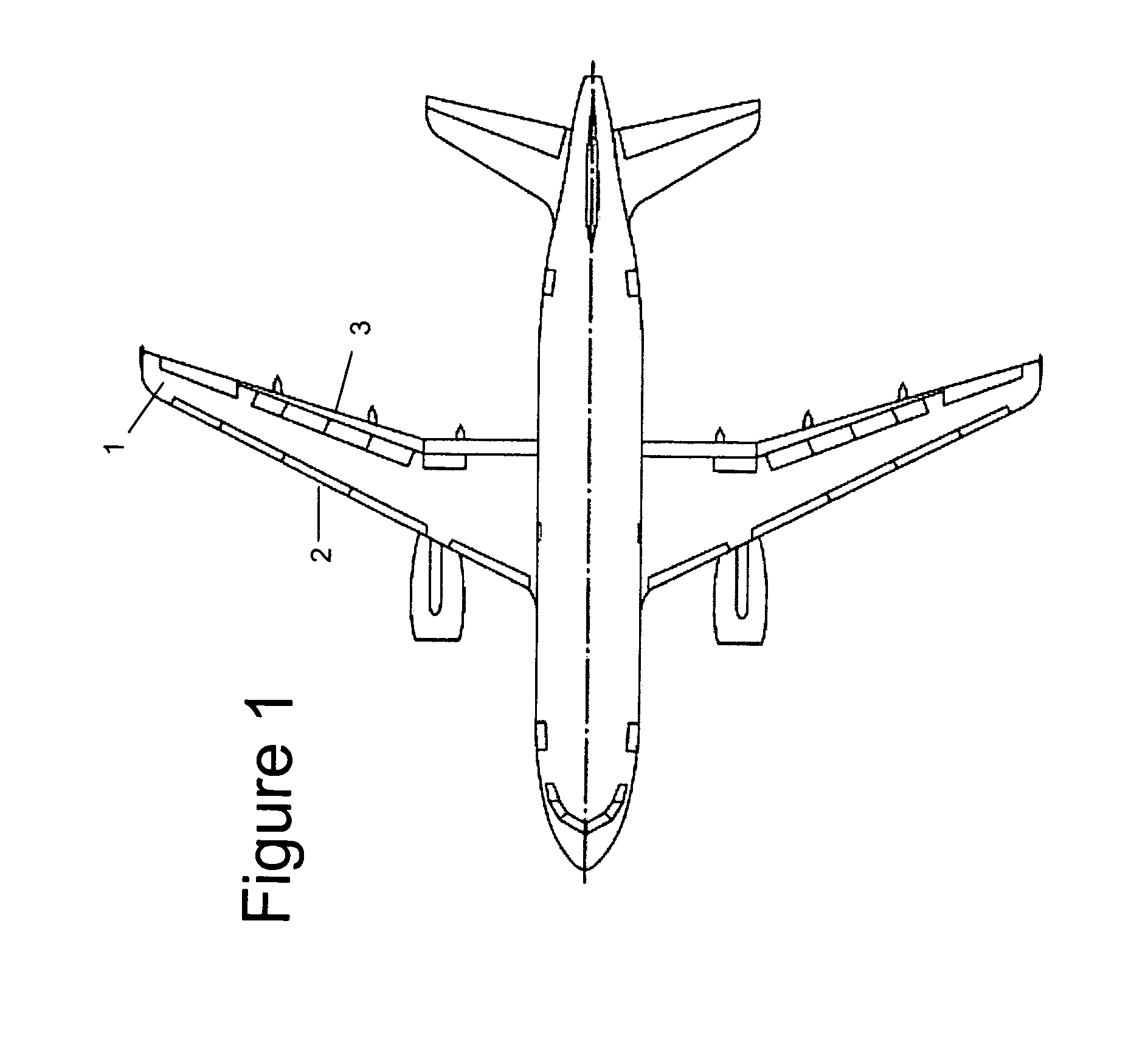
[0021]FIG. 1 is a plan view of an aircraft with natural laminar flow wings 1. Each wing has a leading edge 2 and a trailing edge 3.

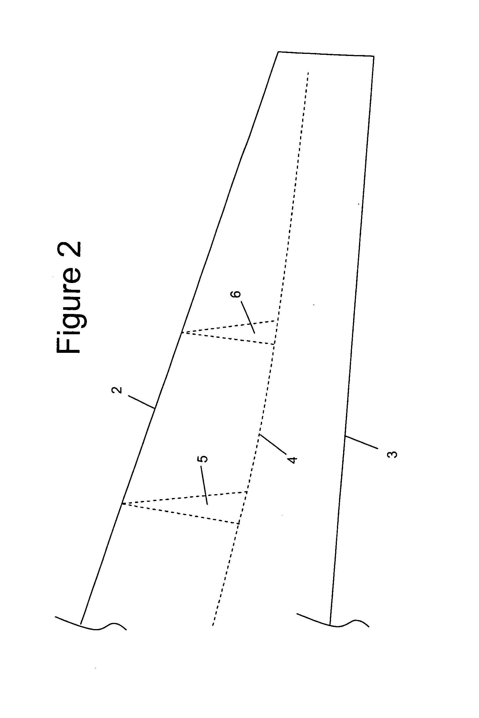
[0022]The wings are designed so that air flowing over the upper surface experiences a favourable pressure gradient with pressure falling in the direction of air flow over a significant chord-wise extent. Typically the favourable pressure gradient starts towards the leading edge of the wing and ends somewhere between 30-75% of the chord distance from the leading edge to the trailing edge. Where this favourable pressure gradient exists, the air flow tends to remain laminar. FIG. 2 is a plan view of the wing 1, showing schematically a line 4 where the air flow over the upper surface of the aerofoil becomes turbulent. In this example the air flow over the surface is laminar for about 50% of the chord distance from the leading edge 2 to the trailing edge 3.

[0023]Laminar flow is very sensitive to small surface imperfections and distortion which can result in ...


PUM


Abstract

A method of monitoring the performance of an aerodynamic surface of an aircraft. The aircraft is operated during a non-perturbed measurement period such that the flow of air over the surface is at least partially laminar. A parameter is measured which is indicative of the drag of the surface during the non-perturbed measurement period to provide non-perturbed drag data. Air flow is perturbed temporarily over the surface in a perturbed measurement period so that it undergoes a transition from laminar flow to turbulent flow. The parameter is also measured during the perturbed measurement period to provide perturbed drag data. The degree of laminar flow during the non-perturbed measurement period can then be estimated in accordance with the difference between the perturbed drag data and the non-perturbed drag data. An ice protection system can be used to perturb the air flow.

Description

FIELD OF THE INVENTION[0001]The present invention relates to a method and apparatus for monitoring the performance of an aerodynamic surface of an aircraft, in particular to estimate the degree of laminar flow of air over the surface. The invention is typically, although not exclusively, used to monitor the performance of a natural laminar flow wing or tail surface.BACKGROUND OF THE INVENTION[0002]The deployment of natural laminar flow on aircraft wings and empennage can result in significant savings in drag and hence improved fuel burn. However, laminar flow is very sensitive to small surface imperfections and distortion which can result in premature transition to turbulence. It would therefore be desirable to provide a reliable method of checking the state of laminar flow in flight.SUMMARY OF THE INVENTION[0003]A first aspect of the invention provides a method of monitoring the performance of an aerodynamic surface of an aircraft, the method comprising operating the aircraft durin...

Claims


Application Information

Patent Timeline
Patent Type & Authority Applications(United States)
IPC IPC(8): B64D15/20G01M9/00G06F19/00
CPCG01M9/06B64D15/20
Inventor WOOD, NORMAN
Owner AIRBUS OPERATIONS LTD
Why Eureka
Try Eureka