
Configuration for forming a ventilation aperture

a ventilation aperture and configuration technology, applied in the direction of containers, large containers, printing, etc., can solve the problems of increasing labor and costs, and achieve the effect of reducing cross section, easy production, and easy operation

Inactive Publication Date: 2004-09-14
ARTECH DESIGN PRODN & PLASTIC
View PDF8 Cites 7 Cited by
  • Summary
  • Abstract
  • Description
  • Claims
  • Application Information

AI Technical Summary

Benefits of technology

A particular advantage of the design in accordance with the invention lies in the fact that for the first time, both the wall with the passageway and the sealing piece in the form of the stopper according to the invention can be made as injection-molded formed plastic parts that can be made available with little manufacturing effort or cost. The passageway in the wall, of the ink container of an ink cartridge for an inkjet printer, for example, merely has a round cross section with no ribs or additional depressions as is the case in the state of the art, so that it can be reproducibly created with sufficient high precision using common manufacturing methods. For the sealing piece in accordance with the invention, i.e., the stopper provided with the channel-like depressions, the same holds true as a matter of principle. Specifically, its standard cylindrical form is modified only by the axially continuous channels or grooves that are formed into its outside, which, taking into consideration modern plastic injection-molding manufacturing techniques, can also be carried out with markedly little effort. Sufficiently high precision and reproducibility is likewise assured in every case. Specifically, during the manufacturing of the stopper the depressions are given a larger open cross section than is necessary later for the ventilation apertures formed from it, since the adjustment of this nominal cross section takes place--as has been described earlier--only when it is pressed into the passageway in the housing. The larger open cross section during the manufacturing of the depressions simplifies production when conventional injection molding techniques are used.
In comparison with the state of the art, the use of a sealing piece made of injection-molded plastic has the added advantage that no additional parts such as glass spheres, etc., have to be purchased in addition, and the manufacturing is simpler and less expensive as a result.
Moreover, the design according to the invention has the special advantage that for a given diameter of the passageway in the wall, through the design of the cross section, the depth, the shape and the number of depressions, the amount of oversize, and the choice of elastic material, it is possible to adjust the properties of the ventilation configuration, and thus the best possible adaptation to the given requirements can take place.
Preferably, the channel-like depression is given a V-shaped cross section. This shape is easy to manage in terms of manufacturing technology, and is also especially favorable in terms of the deformation while being pressed into place in the passageway in order to form a fine gap with a defined cross section. The depression can also have a U-shaped or other cross section as well.
The invention also includes the method for manufacturing a ventilation aperture of small cross section in a container wall, specifically, in a ink tank of an inkjet printer as was explained in some detail above. This method makes particular use of knowing how to manufacture an easily produced depression of larger cross section when the stopper is being pressed oversized into a predetermined wall passageway, whereby the depression is squeezed together to the nominal dimension of the cross section of the ventilation aperture while reducing the cross section.
The fastening of the stopper, which, like the wall, is made of a thermoplastic, can be carried out very easily by means of ultrasonic welding, whereby only an ultrasonic excitation of the container wall must be carried out such as is already being done, for example, when the container wall is placed onto and ultrasonically welded to a container. Because of the mass ratios of wall and stopper, they are placed into relative movement, as a result of which they are nondetachably welded to one another.

Problems solved by technology

A simple, formed plastic part cannot be used in this configuration, which of course results in increased labor and costs.

Method used


Image

  • Configuration for forming a ventilation aperture
  • Configuration for forming a ventilation aperture
  • Configuration for forming a ventilation aperture

Examples


Embodiment Construction

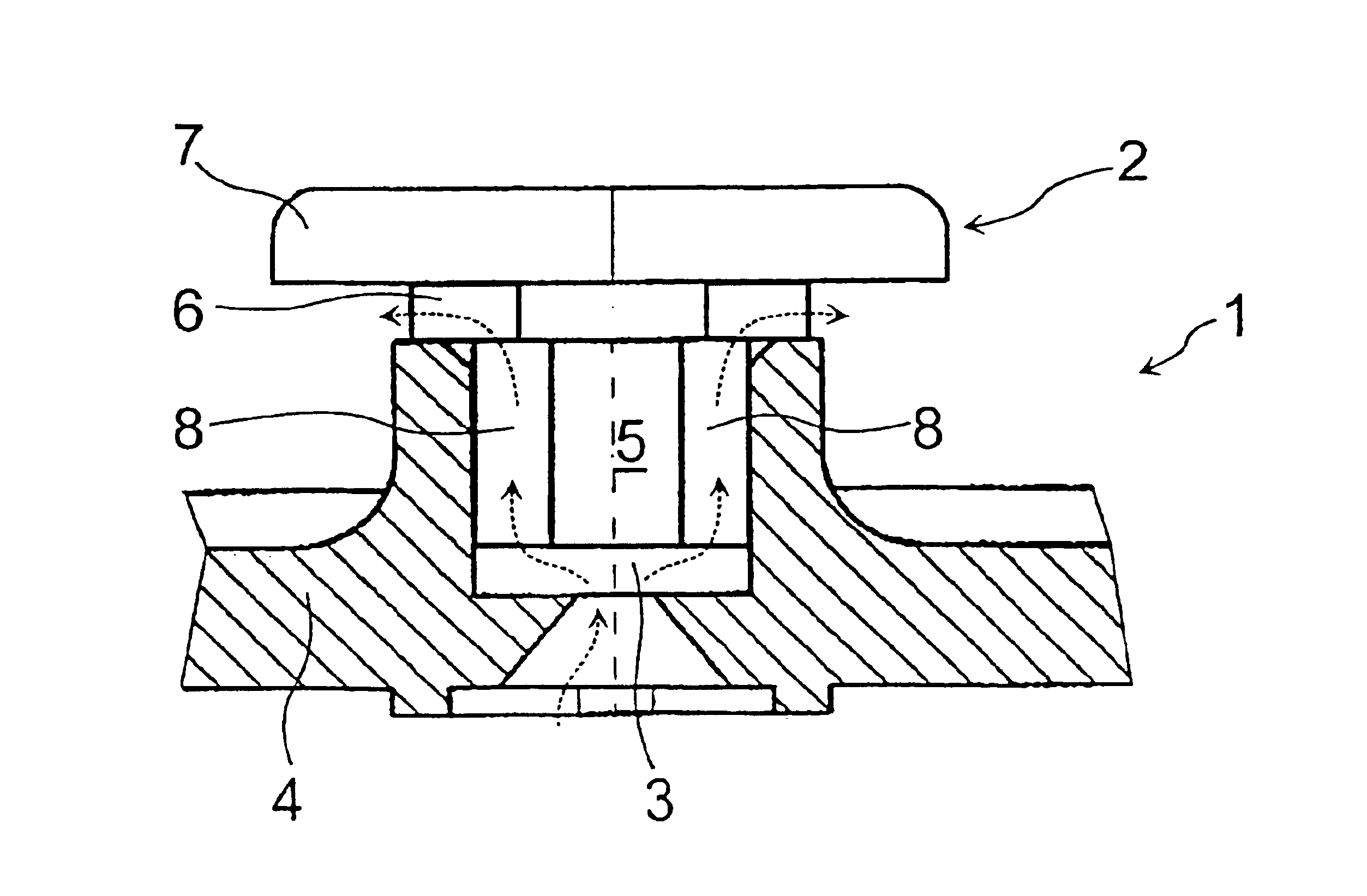
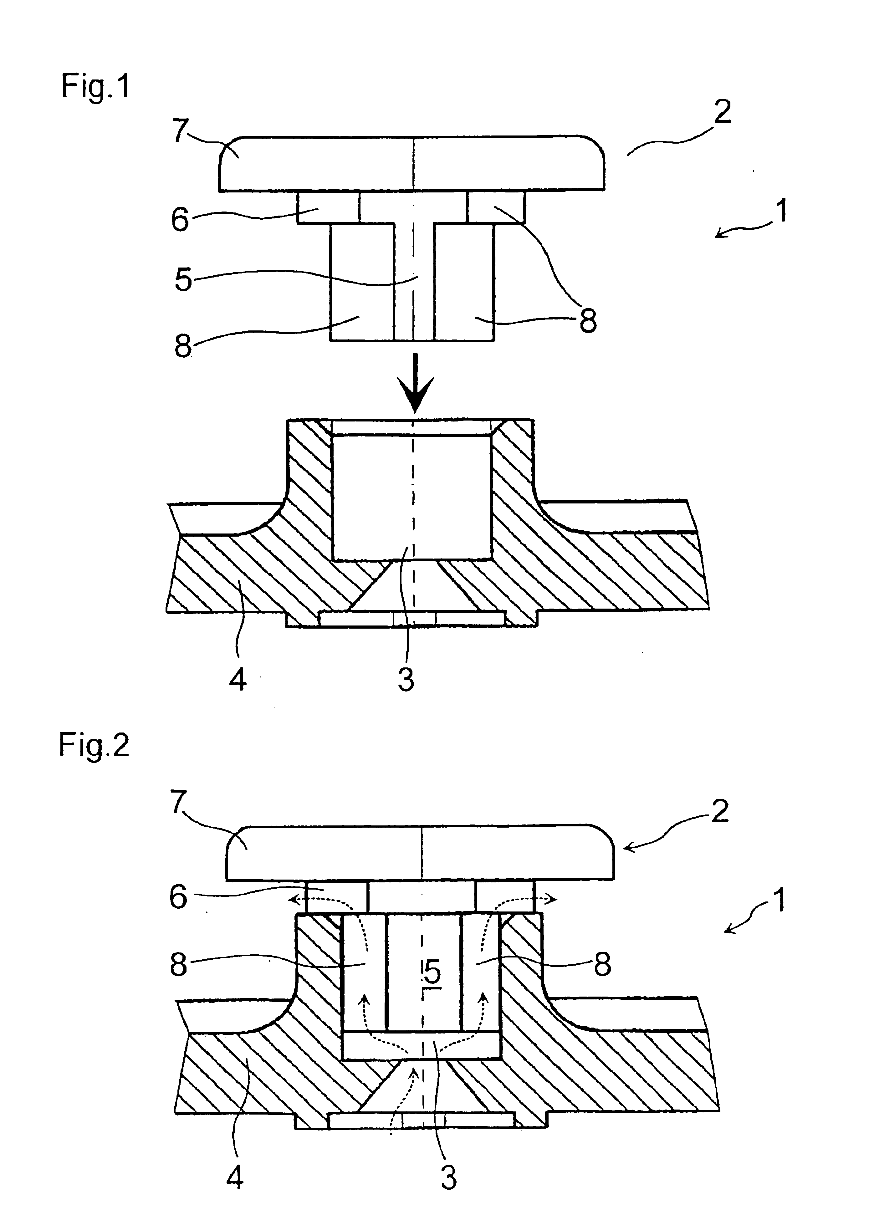
The ventilation configuration in accordance with the invention is shown in side section view in FIG. 1 and FIG. 2, once in the disassembled state (FIG. 1) and once in the assembled state (FIG. 2), whereby it is provided in its entirety with reference number 1. It is formed from a sealing piece 2 and a passageway 3 in the wall 4 of an ink tank (not shown in more detail) of an ink cartridge for an inkjet printer. As is shown in the drawings, the sealing piece 2 is pressed into the passageway 3 from the inside of the container.

The passageway 3, which is shown in section, is cylindrical in shape with a defined inside diameter and smooth inside wall. It is formed into the wall 4, which is an injection-molded plastic part.

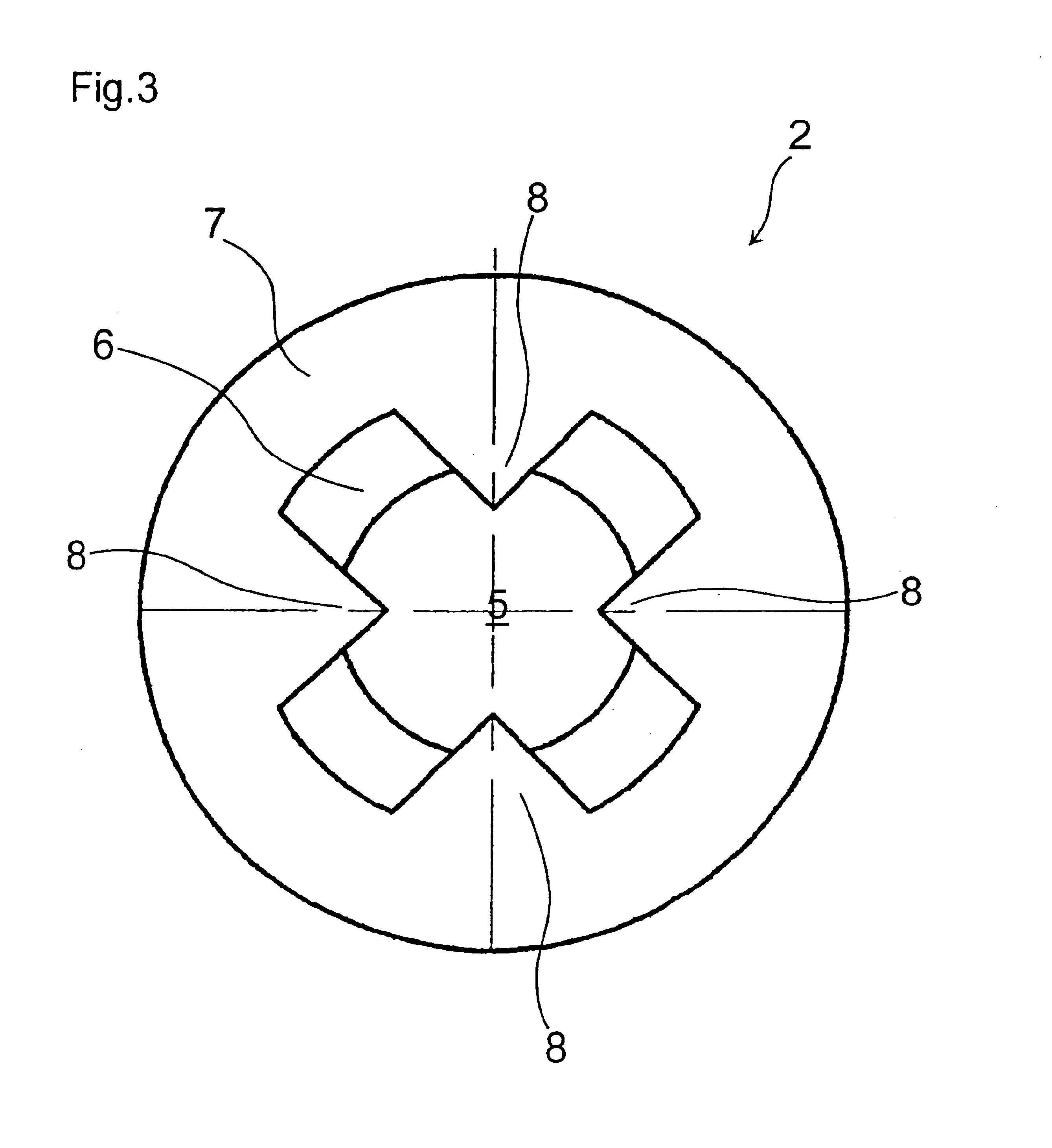
The sealing piece 2 is also a one-piece injection-molded plastic part, made, for example, of polypropylene. It has a cylindrical stopper 5 that has an axial discharge section 6 formed towards the top of the drawing, and head section 7 formed onto that. The head 7 has a l...


PUM


Abstract

The invention pertains to a configuration for forming a ventilation aperture having a small cross section, whereby a sealing part is placed in a passageway and the ventilation aperture is formed between the sealing part and the inner wall of the passageway. In order to simplify manufacturing and, in particular, make possible the use of injection-molded plastic parts throughout, the invention suggests that the sealing part should have a cylindrical stopper that is made of an elastically deformable material and can be inserted into the passageway, and has in its surface shell at least one axially continuous, channel-like depression, the outside diameter of which, when in the unstressed state, is oversized in comparison with the inside diameter of the passageway.

Description

The invention pertains to a configuration for forming a ventilation aperture having a small cross section, whereby a sealing part is placed in a passageway and the ventilation aperture is formed between the sealing part and the inner wall of the passageway. In particular, this pertains to the ventilation aperture in the ink tank of an inkjet printer ink cartridge.PRIOR ARTIn order to equalize pressure with the environment, liquid-filled containers from which liquid is to be drawn off during operation have a ventilation aperture to allow ambient air to flow in, since the liquid in the container would otherwise form a restraining negative pressure. This is especially applicable for the ink tanks used in ink cartridges for inkjet printers. A uniform, well-defined ink supply to the inkjet printhead presupposes pressure relationships within narrowly defined tolerance ranges. This means that an amount of air corresponding to the amount of ink that was withdrawn should flow in through the ...

Claims


Application Information

Patent Timeline
IPC IPC(8): B41J2/175B65D51/16
CPCB41J2/17503B41J2/17553B41J2/17556B65D51/1611Y10T137/0874
Inventor MICHELE, HELMUTKLEIN, DIRKBUSCH, PETER
Owner ARTECH DESIGN PRODN & PLASTIC
Learn More