
Low-light-transmittance copper-clad laminate and preparation method

A light transmittance, copper-clad laminate technology, applied in chemical instruments and methods, printed circuit manufacturing, circuit substrate materials, etc., can solve the problems of complex preparation methods, high cost, low thermal expansion coefficient of copper-clad laminates, etc., and achieve the preparation method Simple, low light transmittance, good practical effect

Inactive Publication Date: 2019-09-06
厦门市三熠智能科技有限公司
View PDF5 Cites 6 Cited by
  • Summary
  • Abstract
  • Description
  • Claims
  • Application Information

AI Technical Summary

Problems solved by technology

[0004] The Chinese Invention Patent with the authorized notification number CN102924869B discloses the method of adding black modified silicon dioxide to the copper clad laminate glue. The obtained copper clad laminate has a low thermal expansion coefficient and has little effect on insulation, but the light transmittance is not low enough.
[0005] The Chinese Invention Patent with the authorized notification number CN103571156B discloses a thermosetting resin composition, including a thermosetting resin and an inorganic filler coated with graphene oxide or graphene. Although it can effectively reduce the light transmittance of the copper clad laminate, the preparation method complex and costly

Method used


Image

  • Low-light-transmittance copper-clad laminate and preparation method
  • Low-light-transmittance copper-clad laminate and preparation method
  • Low-light-transmittance copper-clad laminate and preparation method

Examples


Embodiment approach

[0036] raw material:

[0037] (A) Epoxy resin, the epoxy equivalent of the epoxy compound is 170~950g / eq. Epoxy resin can be selected from following two kinds of epoxy resins of A-1 and A-2,

[0038] (A-1) Epoxy resin GESR901 of Hongchang Electronic Materials Co., Ltd., epoxy equivalent 450-500g / eq;

[0039] (A-2) o-cresol novolac epoxy resin CNE-202 of Taiwan Changchun Artificial Resin Factory Co., Ltd., epoxy equivalent 202g / eq;

[0040] (B) epoxy resin solidifying agent is dicyandiamide, is purchased from Ningxia Jiafeng Chemical Co., Ltd.;

[0041] (C) The curing accelerator is 2-methylimidazole, purchased from Shikoku Chemical Industry Co., Ltd.;

[0042] (D) Filler, the filler can be selected from the following three types, namely D-1, D-2 and D-3,

[0043] (D-1) Microsilica powder (average particle size is 3 μm, purity is more than 99%);

[0044] (D-2) aluminum hydroxide (average particle diameter is 2 μ m, purity more than 99%);

[0045] (D-3) Degussa carbon black ...

Embodiment 1~5 and comparative example 1~5

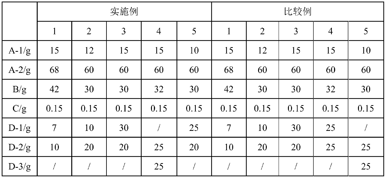
[0056] The raw materials A-1, A-2, B, C, D-1, D-2, D-3, E-1, E-2, F and G in the above embodiment were prepared according to the formula in Table 1. copper plate.

[0057] Table 1 Recipe

[0058]

[0059]

[0060] Among them, Examples 1-5 are copper-clad laminates in which the intermediate layer prepared according to the solution of the present invention contains graphene, and the upper and lower layers are insulating layers. Comparative Examples 1-5 are copper clad laminates obtained by heating and pressing two identical single layers.


PUM

PropertyMeasurementUnit
Epoxy equivalentaaaaaaaaaa

Abstract

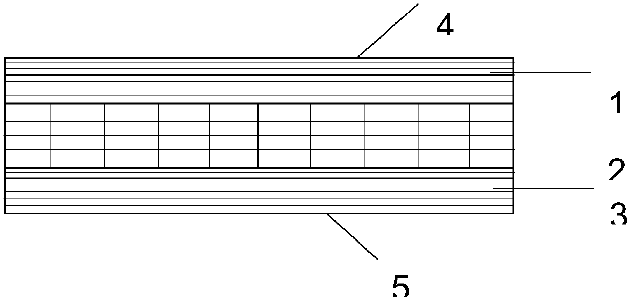
The invention belongs to the field of copper-clad laminates, and particularly relates to a low-light-transmittance copper-clad laminate and a preparation method. The copper clad laminate comprises a first insulating layer, a second opaque layer and a third insulating layer, the first insulating layer is arranged on the upper surface of the second opaque layer, and the third insulating layer is arranged on the lower surface of the second opaque layer; copper foil is attached to at least one surface of the upper surface of the first insulating layer and the lower surface of the third insulatinglayer. The low-light-transmittance copper-clad laminate and the preparation method have the advantages that graphene is added to the middle opaque layer to achieve the purpose of low light transmittance; moreover, the upper and lower surfaces of the middle layer are provided with the insulating layers respectively, the purpose of low light transmittance can be achieved, the electrical performanceof the copper-clad laminate cannot be influenced, and the practicality is high.

Description

technical field [0001] The invention relates to the field of copper-clad laminates, in particular to a copper-clad laminate with low light transmittance and a preparation method thereof. Background technique [0002] Copper clad board is made by soaking electronic glass fiber cloth or other reinforcing materials in resin liquid, curing it into a thin layer, covering its upper surface or upper and lower surfaces with copper foil, and hot pressing at a certain temperature and pressure. A plate-shaped material is called copper clad laminate (Copper Clad Laminate, CCL), referred to as copper clad laminate. Copper-clad laminate is the basic material for manufacturing printed circuit boards (PCB for short), and PCB is one of the important components of the electronics industry. Almost every kind of electronic equipment, ranging from electronic watches and calculators to large computers, communication electronic equipment, and military weapon systems, as long as there are electron...

Claims


Application Information

Patent Timeline
IPC IPC(8): B32B15/092B32B15/20B32B15/18B32B27/06B32B27/20B32B27/26B32B27/38B32B37/06B32B37/10C08L63/00C08K3/04C08K3/36C08K3/22C08K7/14C08J5/24H05K1/03H05K3/02
CPCB32B15/092B32B15/18B32B15/20B32B27/08B32B27/20B32B27/26B32B27/38B32B37/06B32B37/10B32B2264/0214B32B2264/102B32B2264/104B32B2264/108B32B2307/202B32B2307/206B32B2307/412B32B2457/08C08J5/24C08J2363/00C08K3/04C08K3/042C08K3/22C08K3/36C08K7/14C08K2003/2227H05K1/036H05K3/022C08L63/00
Inventor 杨虎黄强黄鸿邹良茂
Owner 厦门市三熠智能科技有限公司
Learn More