Image pickup module and manufacturing method of image pickup module

The technology of a camera module and manufacturing method is applied in the direction of optical filter for photography, image communication, radiation control device, etc. It can solve the problems of poor impact resistance, blurred focus of incident light, and no installation process, etc., and achieves Effect of improving impact resistance and improving path accuracy

Inactive Publication Date: 2006-06-07
SHARP KK
View PDF2 Cites 11 Cited by
  • Summary
  • Abstract
  • Description
  • Claims
  • Application Information

AI Technical Summary

Problems solved by technology

[0006] However, in the structure disclosed in Japanese Patent Laid-Open No. 2000-125212, since the surface of the substrate is used as a positioning reference, mounting accuracy when the imaging element is mounted on the substrate is required, and at the same time, it is required to mount the lens holder holding the lens on the substrate. Position accuracy when on the substrate, but not necessarily fully simplify the installation process and improve focus accuracy
Although the surface accuracy of the substrate surface used as a positioning reference is important, since the surface of the substrate usually has unevenness, it needs to be smoothed, and there is a problem that the cost increases.
[0007] On the other hand, in the structure disclosed in JP-A-2001-351997, since the transparent plate and the lens holder are bonded, the bonding stress acts on the transparent plate. Cracks, and there is a danger that the transparent plate will be peeled off from the imaging element
Especially when used in mobile phones that require high impact resistance, it is not good
When the thermal expansion coefficients of the transparent plate and the lens holder are greatly different, the transparent plate is deformed due to the difference in thermal expansion coefficient during bonding, and the path of the incident light is shifted due to this influence, resulting in a problem of blurred focus.

Method used


Image

  • Image pickup module and manufacturing method of image pickup module
  • Image pickup module and manufacturing method of image pickup module
  • Image pickup module and manufacturing method of image pickup module

Examples


Embodiment approach 1

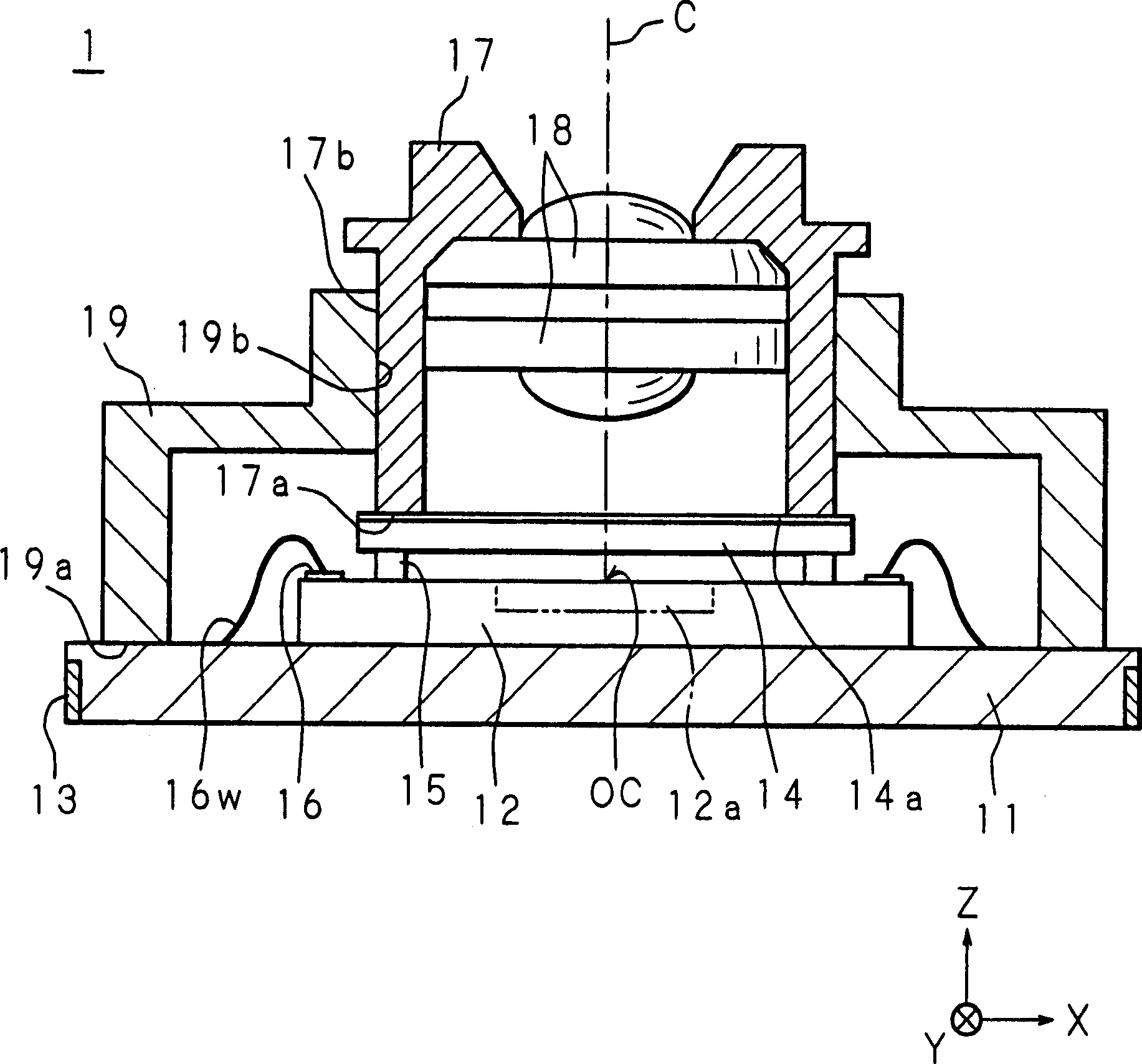
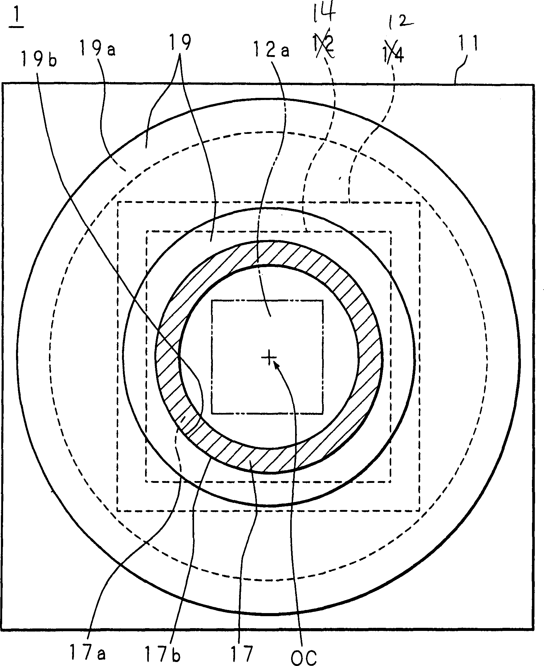
[0060] figure 1 is a side sectional view showing the structure of the camera module according to Embodiment 1 of the present invention, figure 2 It is a plan view of the camera module according to Embodiment 1 of the present invention viewed from the light incident side. In order to easily understand the positional relationship of the imaging element, the lens holder and the cover which are the features of the present invention, in figure 2 Some structural elements are omitted for representation.

[0061] In the camera module 1 according to Embodiment 1 of the present invention, the camera element 12 is diced and bonded to the substrate ( Substrate )11 on one surface. The imaging element 12 is a semiconductor device such as a CCD or a CMOS imager, and its structure is such that the light receiving unit 12a is placed in the center of the chip, and peripheral circuits such as a readout circuit for reading out a signal based on the amount of light detected by the light rece...

Embodiment approach 2

[0083] In Embodiment 1, a method was described in which the optical position of the lens in the XY direction and the Z direction is restricted by a cover and a lens holder, but a lens holder functioning as a cover may also be used, as is the case in Embodiment 2.

[0084] Figure 7 It is a side sectional view showing the structure of the camera module according to Embodiment 2 of the present invention.

[0085] The camera module 2 according to Embodiment 2 of the present invention is provided with: the lens holder ( fixed part )27. A lens 28 that guides the path of incident light to the light receiving portion 12 a of the imaging element 12 is fixed at a predetermined position on the lens holder 27 . The lens holder 27 has a stepped portion 27b having the function of the contact portion of the present invention, the stepped portion 27b engages with the edge of the transparent plate 14, and the foot portion 27a is fixed with an adhesive 63 in a state where the stepped portio...


PUM


Abstract

The camera module (1) of the present invention is provided with a tubular cover (19) and a lens holder (17). The cover (19) is fixed (bonded) to the substrate (11) with its legs (19a) in contact with the surface of the substrate (11). Moreover, the lens holder (17) is inserted into the inner surface (19b) of the cover (19), the lens holder (17) is in contact with the transparent plate (14) at its foot (17a) and its outer surface (17b) is in contact with the inner surface of the cover In the state, the outer surface (17b) of the lens holder (17) is fixed (bonded) on the inner surface (19b) of the cover (19). A lens (18) guiding the path of incident light to the light receiving portion (12a) of the imaging element (12) is fixed at a predetermined position on the lens holder (17).

Description

technical field [0001] The present invention relates to a camera module and a method of manufacturing the camera module in which an imaging element having a light receiving unit and a lens for imaging incident light on the light receiving unit are modularized (integrated). Background technique [0002] Imaging elements such as CCDs and CMOS imagers, which are semiconductors, are being used in various fields. In particular, in addition to the communication function, a mobile phone with a camera, which has a camera function added by mounting an imaging element, is widely put into practical use. With the miniaturization, thinning, and weight reduction of products such as mobile phones with cameras and digital cameras, camera modules in which imaging elements and lenses are modularized are also being put into practical use. [0003] In conventional imaging modules, an imaging element is disposed on a substrate, and the imaging element is electrically connected to wiring on the ...

Claims


Application Information

Patent Timeline
Patent Type & Authority Applications(China)
IPC IPC(8): H04N5/225G02B7/02G03B11/00G03B17/02H01L27/14H01L27/148H01L31/02H04N5/335
CPCG02B7/02H01L27/14618H01L2224/48091H01L27/14632H01L27/14687H01L27/14625H04N23/57H04N23/55H01L2924/00014H01L27/146
Inventor 广冈章吾
Owner SHARP KK
Why Eureka
Try Eureka