Mounting device for holding object

Inactive Publication Date: 2012-03-01
SUPA TECH
View PDF5 Cites 16 Cited by
  • Summary
  • Abstract
  • Description
  • Claims
  • Application Information

AI Technical Summary

Benefits of technology

[0007]A primary objective of the present invention is to provide a mounting device for a communication product that is easy to adjust the viewing angle of the communication product. The mounti

Problems solved by technology

It is inconvenient for the users to oper

Method used


Image

  • Mounting device for holding object
  • Mounting device for holding object
  • Mounting device for holding object

Examples


Embodiment Construction

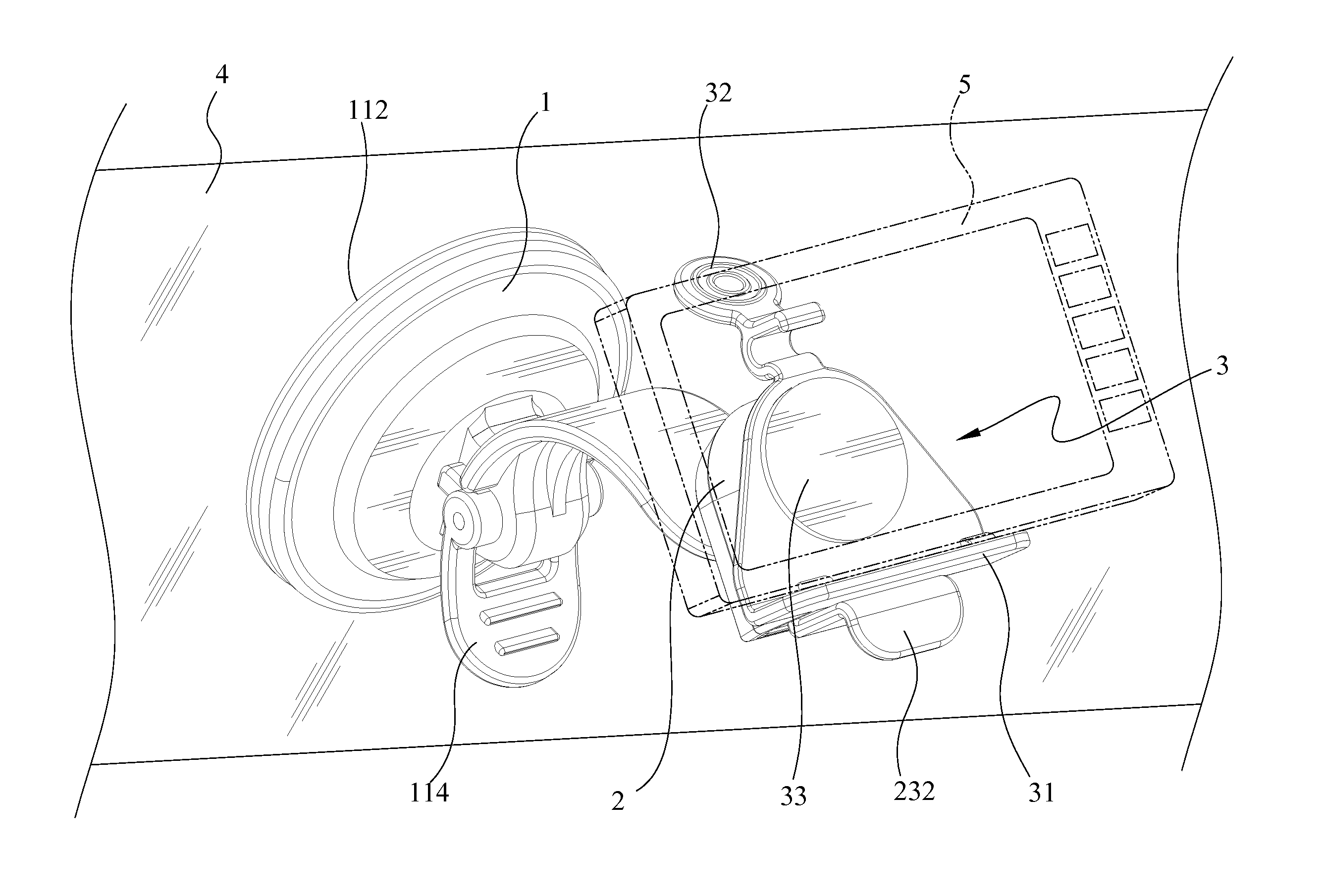
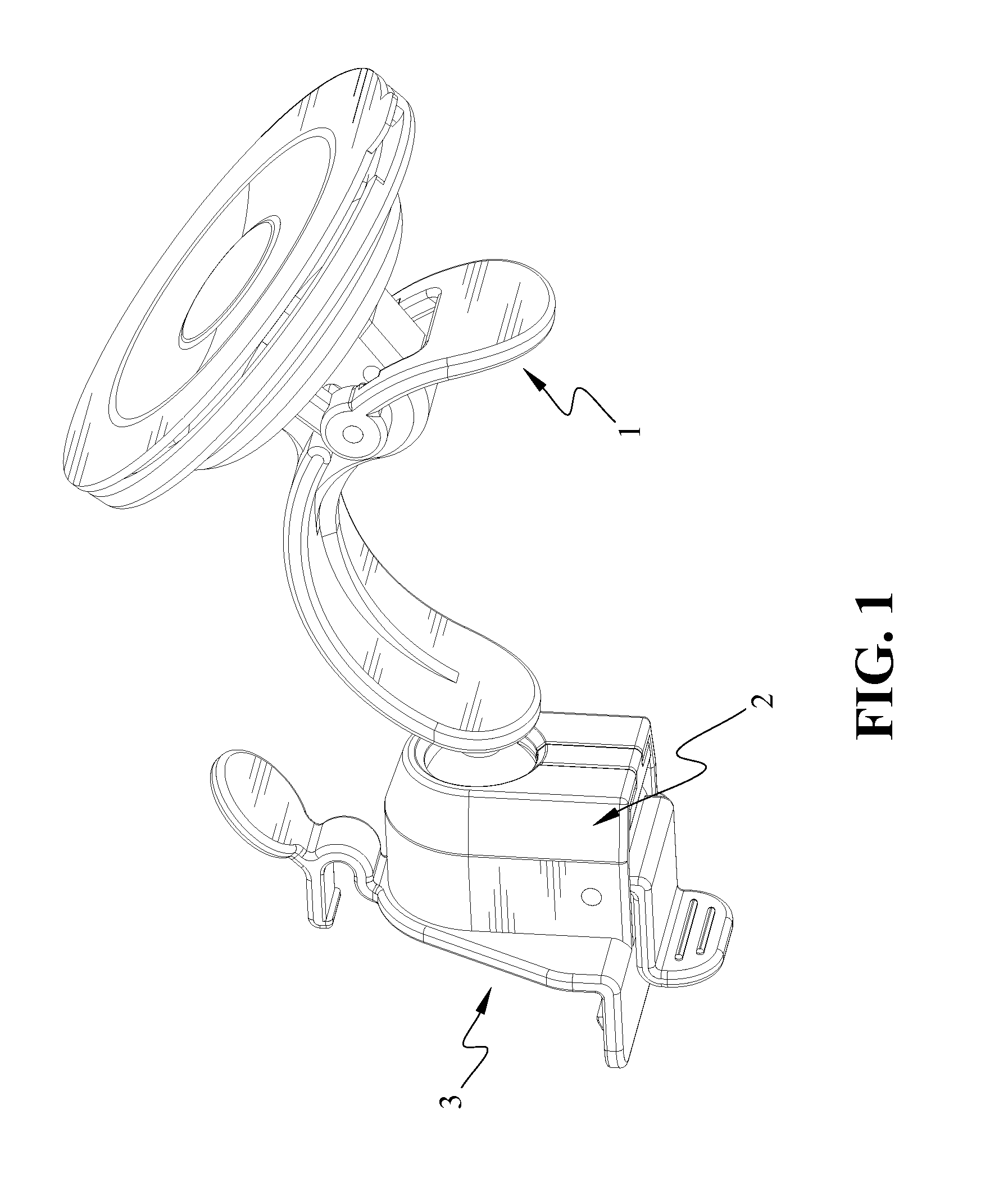
[0020]With reference to the drawings and in particular to FIG. 1, a mounting device for holding an object in accordance with the present invention comprises an attaching unit 1, a securing unit 2, and a holding unit 3. The securing unit 2 and the holding unit 3 can simultaneously move relative to the attaching unit 1, thereby adjusting angular position of the object.

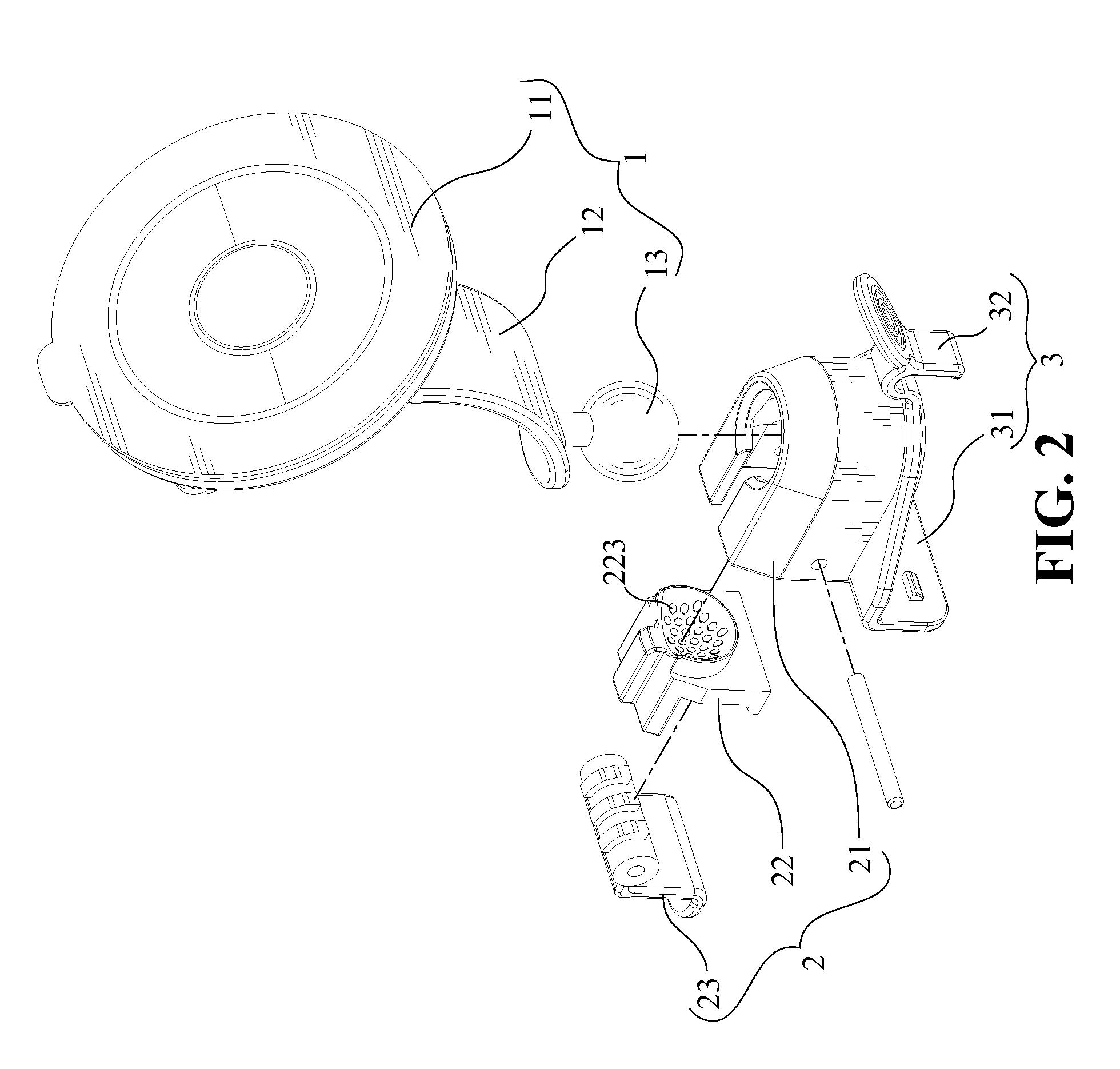
[0021]Referring to FIGS. 2 and 3, the attaching unit 1 comprises a suction disk assembly 11 and a support arm 12 which has a joint member 13 at a free end thereof.

[0022]The suction disk assembly 11 comprises a disk frame 111, a suction disk 112 and a link 113. The link 113 is disposed between and connects the disk frame 111 and the suction disk 112. A U-shaped lever 114 includes two arms 1141 which are pivotably connected to the disk frame 111. Each arm 1141 has a protrusion 1142 and a pin 1143 passes through the two arms 1141, a rear portion of the disk frame 111 and an end of the link 113. The rear portion of the disk ...


PUM


Abstract

A mounting device includes an attaching unit having a suction disk assembly and a support arm which has a joint member on a free end thereof. A securing unit has a hollow case and a movable member disposed in the hollow case so as to define a first chamber and a second chamber in the hollow case. The joint member is received in the first chamber. The hollow case is pivotable relative to the joint member. A pressing member is disposed in the second chamber and can force the movable member to securely fix the joint member between the hollow case and the movable member. A holding unit is connected to the hollow case and a communication product is held by the holding unit. The holding unit is moved with the hollow case and the communication product is adjusted to an optimal angle.

Description

BACKGROUND OF THE INVENTION[0001]1. Field of the Invention[0002]The present invention relates generally to a mounting device, and in particular to a windshield mount or a dashboard mount to hold a communication product.[0003]2. The Prior Arts[0004]Communication products such as cellular phones, PDA's, and GPS devices are used widely and gaining popularity. Users can use the communication products at any place and at any time.[0005]However, when the user drives or takes a vehicle, the user usually puts the communication product on a dashboard mount or a windshield mount. Conventional vehicle mounting device can securely hold the communication product in vehicle, but it needs a switch to control spinning the communication product toward the user and another switch to control rotating the communication product to a pitch angle for better viewing. Therefore, the user has to loosen two switches and then adjust the communication product to an optimal viewing orientation. It is inconvenien...

Claims


Application Information

Patent Timeline
IPC IPC(8): F16B47/00
CPCF16B2/185F16B47/006F16M2200/022F16M11/14F16M13/022F16M11/041
Inventor CHEN, JEONG-SHIUN
Owner SUPA TECH
Why Eureka
Try Eureka