Big data interactive teaching practical training platform facilitating observation angle adjustment
A viewing angle, interactive teaching technology, applied in the field of teaching platforms, can solve the problems of inability to horizontal direction, difficult operation, complex structure, etc., to achieve the effect of easy operation, easy installation, and easy adjustment of the Z-axis height.
- Summary
- Abstract
- Description
- Claims
- Application Information
AI Technical Summary
Problems solved by technology
Method used
Image
Examples
Embodiment 1
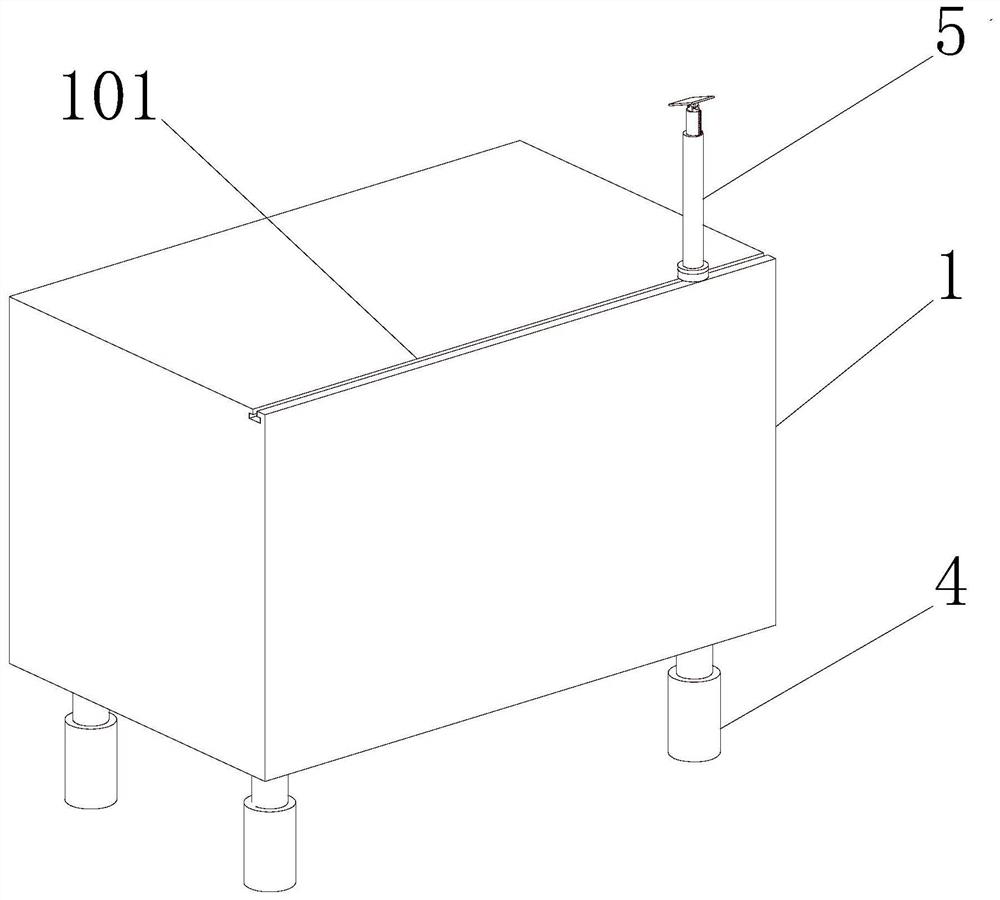
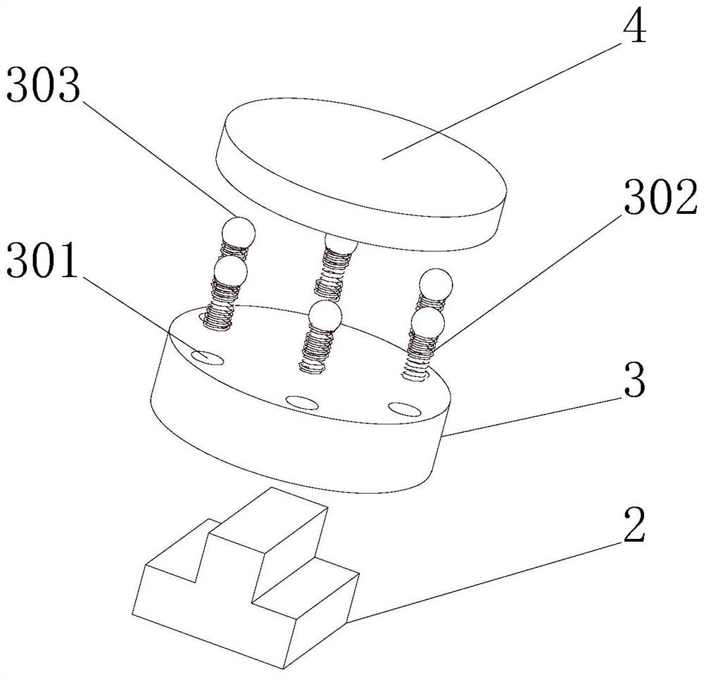
[0035] see Figure 1-4 , the present invention provides a technical solution: a large data interactive teaching and training platform for conveniently adjusting the viewing angle, comprising a main body 1, a first chute 101 is provided on the top outer wall of the main body 1, and the inner wall of the first chute 101 is slidably connected There is a slider 2, the top outer wall of the slider 2 is fixedly connected with a first wheel disc 3, the top outer wall of the first wheel disc 3 is rotatably connected with a second wheel disc 4, and the top outer wall of the first wheel disc 3 is opened There is a groove 301, the bottom of the inner wall of the groove 301 is fixedly connected with a spring 302, and the end of the spring 302 away from the groove 301 is slidably connected with a limit ball 303, and the bottom outer wall of the second wheel disc 4 is provided with a limit groove 401, and the limit ball The outer wall of the limiting ball 303 is slidably connected with the ...
Embodiment 2
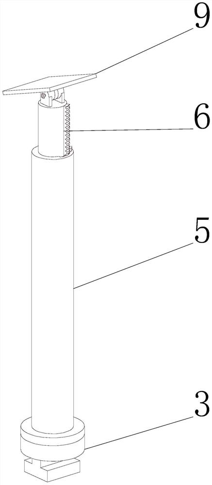
[0038] see Figure 1-6 As shown, on the basis of Embodiment 1, the present invention provides a technical solution: the top outer wall of the second turntable 4 is fixedly connected with a low rod 5, and the top outer wall of the low rod 5 is provided with a second chute 501. The inner wall of the second chute 501 is slidably connected with the ejector rod 6, the inner wall of the second chute 501 is provided with a rack groove 502, the outer wall of the ejector rod 6 is fixedly connected with the second rack 601, and the outer wall of the second rack 601 is connected with the teeth. The inner wall of the rack groove 502 is slidingly connected, and the second sliding groove 501 is fixedly connected with the first rack 503 near the inner wall of the rack groove 502, and the teeth of the first rack 503 mesh with the teeth of the second rack 601. A third chute 6011 is defined on one side of the outer wall of the rack 601 , and the first block 602 is slidably connected to the inne...
Embodiment 3
[0041] see Figure 1-8 As shown, on the basis of Embodiment 1 and Embodiment 2, the present invention provides a technical solution: the top outer wall of the ejector rod 6 is fixedly connected with a first limiting plate 7, and one side of the outer wall of the first limiting plate 7 rotates A pulley 703 is connected, and the outer wall of the pulley 703 away from the first limiting plate 7 is rotatably connected with a second limiting plate 8, and the outer walls of the first limiting plate 7 and the second limiting plate 8 are provided with first six sides. Screw hole 701, the inner wall of the first hexagonal screw hole 701 is plugged with connecting rod 702, and the outer wall of the pulley 703 near the second limit plate 8 is provided with a second hexagonal screw hole 7031, and the pulley 703 is close to the first limiter One side of the outer wall of the plate 7 is provided with a circular screw hole 7032, the outer wall of the connecting rod 702 is engaged with the in...
PUM
 Abstract
Description
Claims
Application Information
 - R&D
- Intellectual Property
- Life Sciences
- Materials
- Tech Scout
- Unparalleled Data Quality
- Higher Quality Content
- 60% Fewer Hallucinations
Browse by: Latest US Patents, China's latest patents, Technical Efficacy Thesaurus, Application Domain, Technology Topic, Popular Technical Reports.
© 2025 PatSnap. All rights reserved.Legal|Privacy policy|Modern Slavery Act Transparency Statement|Sitemap|About US| Contact US: help@patsnap.com


