
Image recording apparatus

a technology of image recording and nozzle, which is applied in the direction of electrical equipment, power drive mechanisms, printing, etc., can solve the problems of deteriorating image, changing the position of the nozzle, and causing the disturbance of the nozzle,

Inactive Publication Date: 2012-03-01
FUJIFILM CORP
View PDF2 Cites 1 Cited by
  • Summary
  • Abstract
  • Description
  • Claims
  • Application Information

AI Technical Summary

Benefits of technology

[0011]In consideration of the above-described circumstances, the present invention provides an image recording apparatus that has excellent maintenance efficiency and in which waste paper is kept little.

Problems solved by technology

During acceleration and deceleration of the recording medium, ordinarily recording of images is not performed, but the continuous paper is conveyed also during acceleration and deceleration, so if the number of times of acceleration and deceleration increases, portions where recording is not performed arise in the continuous paper and end up becoming waste paper.
On the other hand, jetting disturbances (position deviation and misfiring) of nozzles change greatly due to deterioration of the head over time and environmental fluctuations.
When image formation that ignores these is performed, image deterioration such as stripe unevenness ends up arising, and there is the fear that the quality level will drop.
However, when information collection needed for maintenance for correcting the jetting disturbances in image recording using continuous paper—that is, test printing for identifying misfiring nozzles and identifying the cause of jetting direction deviations—is performed separately from the current printing, there is the problem that the number of times of acceleration and deceleration increases as described above and waste paper ends up increasing in accompaniment therewith.

Method used


Image

  • Image recording apparatus
  • Image recording apparatus
  • Image recording apparatus

Examples


Embodiment Construction

[0038]An exemplary embodiment pertaining to the present invention will be described below with reference to the drawings.

[0039]

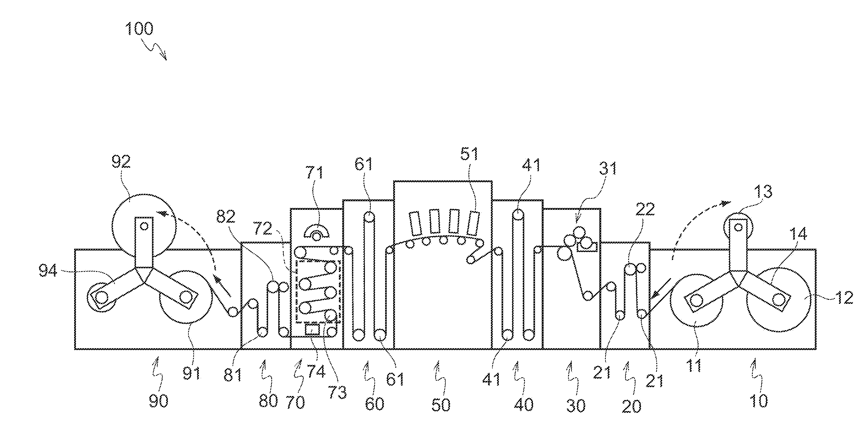
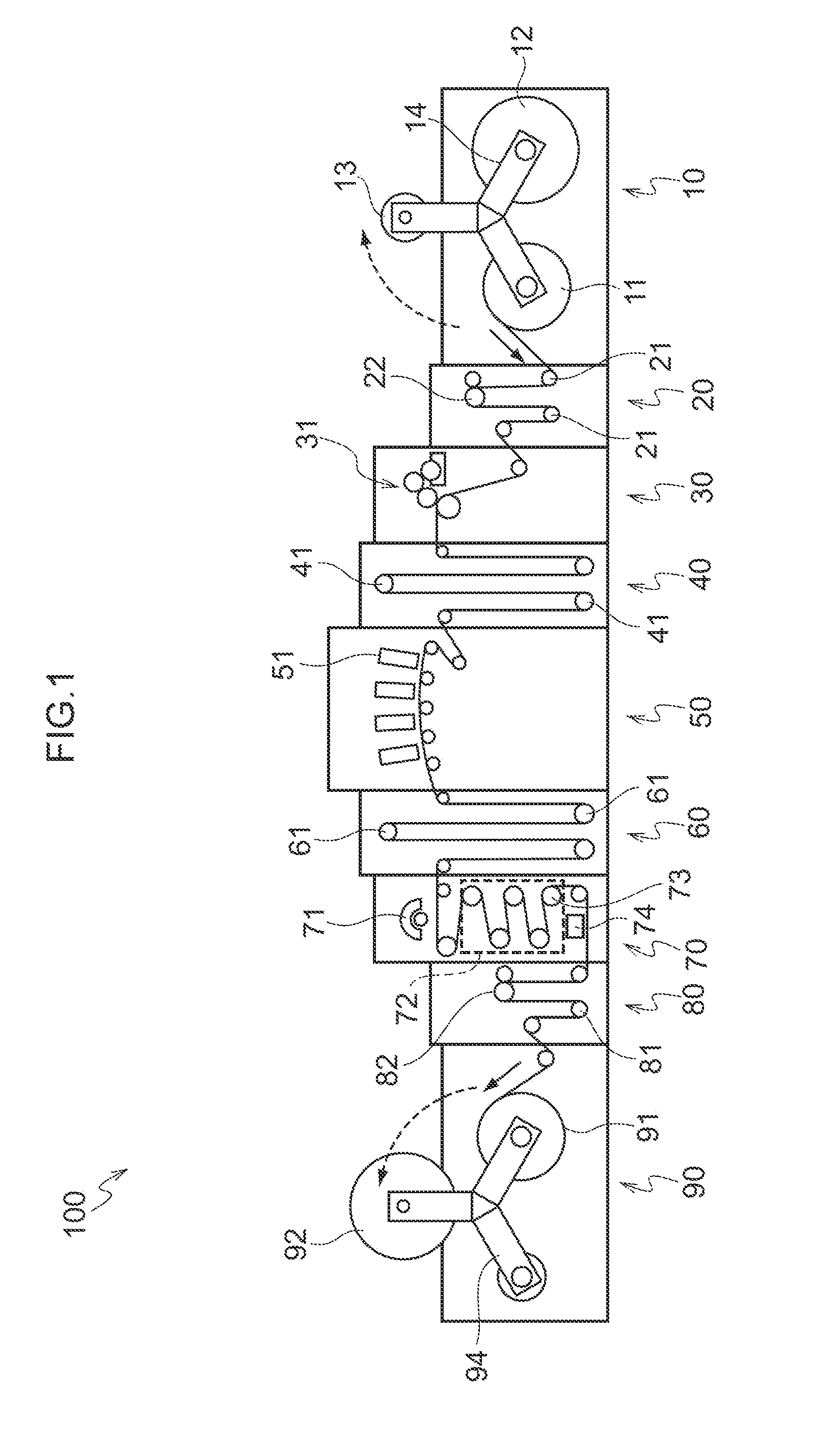
[0040]As shown in FIG. 1, in an image recording apparatus 100 pertaining to the present exemplary embodiment, a feed section 10 that feeds and conveys a web (continuous paper) P serving as a recording medium is disposed on an upstream side in a conveyance direction of the web P. On the conveyance direction downstream side of this feed section 10, an infeed section 20, a process liquid applying section 30, a first drying section 40, an image forming section 50, a second drying section 60, a fixing and reading section 70, an outfeed section 80, and a collecting section 90 are sequentially disposed along the conveyance direction of the web P. The infeed section 20 pulls out the web P from the feed section 10 and temporarily stores the web P. The process liquid applying section 30 applies a process liquid to a recording surface of the web P. The first drying sec...


PUM


Abstract

An image recording apparatus includes: a conveying section that accelerates a long-length recording medium to a predetermined speed, conveys the long-length recording medium, and decelerates the long-length recording medium to a stopped state; a recording section that records an image on the recording medium, and forms a first test pattern on the recording medium after the image is recorded at a time of deceleration of the recording medium; a reading section that reads the image that the recording section has recorded and the first test pattern that the recording section has formed; an image converting section that converts inputted image data into image data that the recording section outputs; a maintenance section that performs maintenance of the recording section; and a controller that decides, on the basis of first data obtained by reading the first test pattern, whether or not the maintenance is needed and the content thereof.

Description

CROSS-REFERENCE TO RELATED APPLICATION[0001]This application claims priority under 35 USC 119 from Japanese Patent Application No. 2010-191274 filed on Aug. 27, 2010, the disclosure of which is incorporated by reference herein.BACKGROUND[0002]1. Technical Field[0003]The present invention relates to an image recording apparatus.[0004]2. Related Art[0005]Conventionally, in image recording apparatus that record character information, images, and so forth on a recording medium by methods such as conveying a recording medium such as a web (continuous paper) in a conveyance direction and jetting ink droplets or the like from a head that opposes a recording surface or making impacts by the dot, acceleration and deceleration of the recording medium become necessary a lot.[0006]During acceleration and deceleration of the recording medium, ordinarily recording of images is not performed, but the continuous paper is conveyed also during acceleration and deceleration, so if the number of times ...

Claims


Application Information

Patent Timeline
IPC IPC(8): H04N1/40
CPCB41J2/16579B41J25/308B41J2/2146
Inventor YAMANOBE, JUN
Owner FUJIFILM CORP
Learn More